Content
In the field of mechanical power transmission, the primary goal is to manage forces while facilitating movement. Ball bearings are the most common solution to this challenge. While they all share the common trait of using spheres as rolling elements, the internal architecture of these bearings varies significantly to handle different directions of force. To understand these types, we must first define the two types of loads: radial loads, which act perpendicular to the shaft, and axial loads, which act along the path of the shaft.
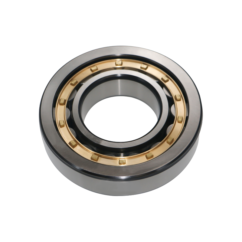
Deep groove ball bearings are the most prevalent type used in the global industry. Their design is characterized by raceway grooves on both the inner and outer rings that have circular arcs slightly larger than the radius of the balls.
Design and Functionality
The “deep” nature of these grooves allows the balls to remain seated even when subjected to high rotational speeds. This geometry creates a stable contact point that can manage radial forces exceptionally well. Furthermore, because the walls of the grooves are high, these bearings can also support a fair amount of axial thrust from either direction.
Key Advantages
Angular contact ball bearings are designed for more complex mechanical environments where forces do not come from a single direction. The raceways of the inner and outer rings are displaced relative to each other along the bearing axis.
The Mechanics of the Contact Angle
The defining feature of this bearing is the contact angle. This is the angle between the line joining the contact points of the ball and the raceways in the radial plane. This design allows the bearing to support “combined loads,” which are simultaneous radial and axial forces.
Single Row vs. Double Row
One of the greatest challenges in large-scale machinery is maintaining perfect alignment. When a long shaft rotates, it may bend or flex under its own weight or the weight of the load. Standard bearings would experience extreme stress and fail under these conditions.
Spherical Outer Raceway
The self-aligning ball bearing solves this through its unique outer ring. The inner surface of the outer ring is ground into a perfect sphere. This allows the inner ring, the cage, and the two rows of balls to swivel together.
Operational Benefits
While most bearings are designed to handle forces coming from the side, thrust ball bearings are built to handle forces pushing directly against the end of the shaft.
The Sandwich Construction
A thrust ball bearing consists of two flat plates, often called washers. One is the shaft washer (attached to the rotating shaft), and the other is the housing washer (attached to the stationary base). The balls are held in a cage between these two plates.
Critical Limitations
It is vital to note that thrust ball bearings cannot handle any radial loads. If a side force is applied, the washers will shift, and the bearing will likely fall apart or jam. Because of this, they are often used in conjunction with a separate radial bearing that manages the side-to-side stability of the shaft.
The table below summarizes the design priorities of these four fundamental types.
| Bearing Category | Load Direction Priority | Construction Type | Misalignment Capability |
|---|---|---|---|
| Deep Groove | Radial and Moderate Axial | Single Unit | Very Low |
| Angular Contact | Combined (Radial and Axial) | Single or Paired | Low |
| Self-Aligning | Radial and Low Axial | Dual Row | Very High |
| Thrust Ball | Pure Axial | Separable Washers | Low |
In mechanical engineering, performance is measured by how effectively a component handles speed, load, and environmental stress. This chapter breaks down the operational characteristics of the primary ball bearing types to help determine which design is best suited for specific technical requirements.
Load capacity is divided into two categories: static and dynamic. Dynamic load capacity refers to the stress a bearing can handle while rotating, while static capacity refers to the weight it can support while stationary without permanent deformation of the balls or raceways.
Speed is the enemy of bearing life. As a bearing rotates faster, it generates heat due to the internal friction of the lubricant and the contact between the balls and the cage.
Running accuracy refers to how much the shaft “wobbles” or moves from its intended center during rotation.
The following data provides a high-level comparison of performance metrics based on standard engineering benchmarks.
| Performance Metric | Deep Groove | Angular Contact | Self-Aligning | Thrust Ball |
|---|---|---|---|---|
| Max Rotational Speed | Extremely High | High | Moderate | Low |
| Radial Stiffness | High | Very High | Low | None |
| Axial Stiffness | Moderate | High | Low | Extremely High |
| Low Friction Start | Excellent | Good | Good | Fair |
| Vibration Resistance | Good | Excellent | Fair | Poor |
The physical space available in a machine often dictates the bearing type regardless of the load.
When choosing between these types, an engineer must ask three primary questions:
By analyzing the data in this chapter, it becomes clear that there is no “perfect” bearing, only the “correct” bearing for the specific environment.
While the mechanical design of a bearing dictates how it handles force, the materials used in its construction determine how it survives its environment. As industrial demands have evolved, engineers have moved beyond standard steel to develop specialized variations that can withstand extreme heat, corrosive chemicals, and even vacuum conditions.
The vast majority of ball bearings are manufactured from high-carbon chrome steel. This material is chosen for its exceptional hardness and fatigue resistance. When heat-treated, it provides a tough surface that can withstand the constant rolling pressure of the balls without cracking or deforming.
In industries where hygiene or chemical resistance is mandatory, such as food processing or pharmaceutical manufacturing, stainless steel is the standard.
One of the most significant advancements in recent decades is the development of hybrid bearings. These utilize standard steel rings but replace the steel balls with ceramic spheres, typically made of Silicon Nitride.
Sometimes, the material is less important than the physical footprint of the bearing.
The following table highlights the differences between the three most common material configurations used in modern ball bearings.
| Material Property | Chrome Steel | Stainless Steel | Ceramic Hybrid |
|---|---|---|---|
| Corrosion Resistance | Low | High | Very High |
| Hardness | Very High | High | Extremely High |
| Maximum Operating Temp | Moderate | Moderate | Extremely High |
| Electrical Conductivity | High | High | None (Insulator) |
| Relative Cost | Economical | Moderate | High |
The cage (or retainer) is the component that keeps the balls separated. While often overlooked, the cage material is vital for high-performance applications.
The physical design and material of a ball bearing determine its potential, but the sealing and lubrication determine its actual lifespan. Statistics from the bearing industry suggest that over eighty percent of premature bearing failures are caused by improper lubrication or the ingress of contaminants like dust and moisture. This chapter explores how these “soft” components protect the “hard” steel of the bearing.
To protect the internal raceways and balls, manufacturers offer different levels of enclosure. These are generally classified into shields and seals.
Metal Shields (Z or ZZ)
Shields are typically made of stamped steel and are fixed to the outer ring, extending toward the inner ring without actually touching it.
Rubber Seals (RS or 2RS)
Seals are made of synthetic rubber bonded to a steel insert. Unlike shields, the lip of the seal makes physical contact with the inner ring.
Lubrication serves three purposes: reducing friction, dissipating heat, and preventing corrosion.
The following table summarizes the trade-offs between different bearing protection methods.
| Feature | Open Bearing | Metal Shield (ZZ) | Rubber Seal (2RS) |
|---|---|---|---|
| Contaminant Protection | None | Moderate | Excellent |
| Lubricant Retention | Poor | Good | Excellent |
| Frictional Heat | Lowest | Very Low | Higher |
| Max Speed Rating | 100 Percent | 100 Percent | 60 to 80 Percent |
| Water Resistance | None | Low | High |
A critical but invisible factor in bearing performance is internal clearance. This is the total distance that one bearing ring can be moved relative to the other.
Even the best lubricant has a limited life. Environmental factors can accelerate its degradation:
In modern “Precision Maintenance” programs, the goal is to keep the lubricant clean, cool, and contained. By selecting the correct seal (like a 2RS for a dusty farm environment) and the correct clearance (like C3 for a high-speed motor), the service life of a ball bearing can be extended from months to years.
The final stage in mastering ball bearing technology is understanding how these components behave in the real world. By examining specific industrial case studies and analyzing the common causes of failure, engineers can bridge the gap between theoretical design and practical reliability.
Different sectors prioritize different bearing attributes based on their unique operational challenges.
Automotive Industry: The Hub Unit
In modern vehicles, the wheel hub uses specialized double-row angular contact ball bearings.
Aerospace: Jet Engine Mainshafts
Jet engines require bearings that can survive speeds exceeding thirty thousand revolutions per minute and temperatures that would melt standard lubricants.
Medical Technology: High-Speed Dental Drills
A dental drill is one of the highest-speed applications in the world, often reaching four hundred thousand revolutions per minute.
Despite the precision of their manufacture, bearings eventually reach the end of their fatigue life. However, most fail prematurely due to external factors. The study of these failures is known as “Root Cause Analysis.”
1. Fatigue and Flaking
This is the natural end of a bearing’s life. After millions of rotations, the metal surface begins to crack and “flake” away. If this happens early, it is usually a sign that the bearing was overloaded.
2. Brinelling (Indentation)
This occurs when a bearing is subjected to a massive shock load while stationary, such as hitting a machine with a hammer during installation. The balls are pushed so hard into the raceway that they leave permanent “dents.” This causes the bearing to vibrate and grow louder over time.
3. Electrical Erosion (Pitting)
Common in motors controlled by variable frequency drives, electricity can arc from the inner ring, through the balls, to the outer ring. Each spark melts a tiny amount of metal, creating a “washboard” pattern on the raceway. This is a primary reason for switching to ceramic hybrid bearings.
4. Contamination
If dust or sand enters the bearing, it acts as a grinding paste. The once-smooth balls become dull and undersized, leading to excessive play and eventual total failure of the machine.
The following table serves as a diagnostic tool for identifying bearing issues in the field.
| Symptom | Potential Root Cause | Recommended Solution |
|---|---|---|
| High-pitched whistling | Lack of lubrication | Re-grease or check seal integrity |
| Deep rumbling or vibration | Brinelling or Flaking | Replace bearing; check installation |
| Overheating | Excessive grease or high friction | Verify grease volume and clearance |
| Discoloration (Blue/Brown) | Extreme heat or oil starvation | Improve cooling or oil flow |
| Fine pitting on raceways | Electrical discharge | Use insulated or ceramic bearings |
As we move toward a more connected industrial world, bearings are becoming “smart.” Modern high-end bearings can now be equipped with embedded sensors that monitor temperature, vibration, and rotation speed in real time. This data is sent to a central computer that can predict exactly when a bearing will fail, allowing companies to replace the part during scheduled downtime rather than suffering an expensive, unexpected breakdown.
From the simple deep groove design to the complex ceramic hybrid, ball bearings are a testament to human engineering. They are the essential interface between stationary and moving parts. By selecting the correct type, material, and sealing method, and by understanding the signs of potential failure, we ensure that the machines of the world continue to turn with efficiency and reliability.
The final transition from engineering theory to operational reality occurs during the selection and installation process. Even the highest-quality bearing will fail within hours if it is misapplied or installed with incorrect techniques. This chapter outlines the rigorous steps required to ensure that a bearing reaches its full calculated life expectancy.
When an engineer selects a bearing, they follow a logical hierarchy of needs. This process ensures that the most critical constraints are met first.
A bearing does not simply “sit” on a shaft; it must be held with the correct amount of pressure. This is known as the “fit.”
If a fit is too tight, it will remove the internal clearance of the bearing, causing it to overheat immediately. If it is too loose, the bearing will vibrate, leading to noise and mechanical damage.
Improper installation is responsible for a large percentage of “infant mortality” in bearings (failures that happen shortly after start-up).
The Golden Rule of Mounting
Never apply mounting force through the rolling elements. If you are pressing a bearing onto a shaft, the pressure must be applied only to the inner ring. If you press on the outer ring to get the inner ring onto the shaft, the force travels through the balls, causing microscopic dents known as brinelling.
Thermal Mounting Methods
For larger bearings, mechanical force is often insufficient.
| Action | The Correct Approach (Do) | The Incorrect Approach (Don’t) |
|---|---|---|
| Cleaning | Keep bearings in original packaging until use | Leave bearings exposed on a dirty workbench |
| Lubrication | Use the exact grease type specified by the maker | Mix different types of grease |
| Mounting | Use a dedicated sleeve or induction heater | Use a hammer directly on the bearing rings |
| Inspection | Listen for consistent, smooth sound | Ignore “chirping” or “grinding” noises |
Throughout this guide, we have traveled from the basic geometry of deep grooves to the molecular advantages of ceramics and the practicalities of industrial maintenance. A ball bearing is not a standalone commodity; it is a precision-engineered system. Its success depends on the harmony between its design, its material, its environment, and the human hands that install it.
As the global industry moves toward more sustainable and energy-efficient goals, the role of the ball bearing becomes even more vital. By reducing friction, we reduce energy consumption. By extending bearing life, we reduce material waste. Understanding the different types of ball bearings is, therefore, not just a technical necessity but a contribution to the efficiency of our modern world.
As we look toward the next generation of mechanical systems, ball bearing technology is transforming. The push for carbon neutrality, the rise of electric mobility, and the digital revolution are driving innovations that go beyond traditional steel and grease. This final chapter explores the cutting-edge developments that will define the future of rotational motion.
The transition from internal combustion engines to electric motors has created entirely new requirements for ball bearings. Electric motors operate at significantly higher speeds (often exceeding twenty thousand revolutions per minute) and require components that can handle rapid acceleration.
In the era of the Industrial Internet of Things, the “dumb” bearing is becoming a thing of the past. Smart bearings are now being manufactured with integrated sensors that communicate directly with a factory’s central nervous system.
The bearing industry is increasingly focused on reducing its environmental footprint. This involves both the manufacturing process and the operational efficiency of the product.
The following table summarizes the emerging technologies and their expected impact on industrial performance.
| Emerging Technology | Primary Benefit | Target Industry |
|---|---|---|
| Integrated Sensors | Predictive maintenance and zero downtime | Manufacturing and Robotics |
| Bio-based Greases | Environmental safety and sustainability | Food Processing and Agriculture |
| Graphene-Coated Balls | Near-zero friction and extreme wear resistance | Aerospace and Defense |
| 3D Printed Raceways | Rapid prototyping and custom geometries | Medical and Specialized Racing |
Beyond material changes, the future of ball bearings lies in surface “functionalization.” Using methods like Physical Vapor Deposition, manufacturers can apply coatings that are only a few microns thick but provide incredible benefits.
The humble ball bearing remains one of the most significant inventions in human history. As we have seen throughout this comprehensive guide, the different types of ball bearings—from Deep Groove to Angular Contact and beyond—each play a specific role in supporting the infrastructure of our lives.
As technology advances, the focus will shift from simply “supporting a load” to “providing data and saving energy.” However, the fundamental principle will remain the same: the efficient management of motion through precision engineering. By understanding these components today, we are better prepared for the mechanical challenges of tomorrow.
1. What is the most significant difference between a shield and a seal?
The primary difference lies in physical contact. A shield is a non-contact metal plate that protects the bearing from large debris while maintaining high-speed capabilities and low friction. A seal is a contact component, usually made of rubber, that touches the inner ring to provide a superior barrier against fine dust and liquids, though it increases friction and lowers the maximum speed limit.
2. When should I choose a ceramic hybrid bearing over a standard steel bearing?
You should opt for ceramic hybrid bearings in three specific scenarios: first, in ultra-high-speed applications where the lighter weight of ceramic balls reduces centrifugal force; second, in environments prone to electrical arcing (like electric motors) because ceramic is an insulator; and third, in high-temperature settings where thermal expansion must be minimized.
3. Why can a thrust ball bearing not support radial loads?
Thrust ball bearings are designed with a horizontal sandwich construction, featuring two parallel washers. Because the raceways are flat and oriented to handle vertical or axial pressure, any side (radial) force will cause the washers to slide across one another, potentially causing the balls to pop out of the tracks and leading to immediate mechanical failure.
4. What does a C3 or C4 clearance rating mean on a bearing?
These ratings indicate that the bearing was manufactured with more internal “play” or room between the balls and the raceways than a standard bearing. This extra space is intentional; it allows the components to expand as they get hot during operation without the bearing becoming too tight or seizing up.
5. How does a self-aligning ball bearing correct for a crooked shaft?
The secret is in the outer ring. The internal surface of the outer ring is ground into a continuous spherical shape. This allows the inner ring and the ball assembly to pivot or tilt freely within the outer ring, much like a ball-and-socket joint, while still maintaining smooth rotation.
Product Categories
Contact Us

Jane@ukl-bearing.com
Jenny@ukl-bearing.com
Andy@ukl-bearing.com
Ivy@ukl-bearing.com

+86-510- 88763239
+86-15371057968

No.1 Hehuan Road, Hudai Town, Binhu District, Wuxi City.
Ready to Begin?
Get in Touch

Now!
UKL BEARING
 English
 Español
 русский