 English
 Español
 русский
Core Dimensions and Key Specifications
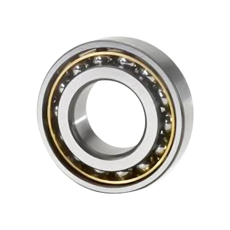
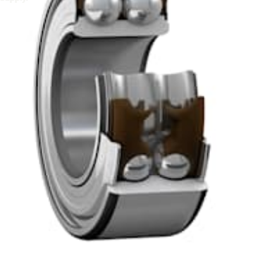
Every design begins with geometry. The 3200 A-2ZTN9/MT33 packs two load paths into one unit. Its layout is equivalent to a pair of single row angular contact ball bearings arranged back to back in an O-type configuration, yet it requires noticeably less axial space. The table below lists the core dimensional data that engineers check first.
| Parameter | Value |
|---|---|
| Bearing type | Double row angular contact ball bearing |
| Bore diameter (d) | 10 mm |
| Outside diameter (D) | 30 mm |
| Width (B) | 14 mm |
| Contact angle | 30° |
| Weight | Approximately 0.051 kg |
| Fillet dimension (r1,2) | Minimum 0.6 mm |
| Pressure point distance (a) | 16 mm |
Reading the bore, outside diameter and width
The 10 mm bore and 30 mm outside diameter define a compact envelope that suits small gearboxes, pump shafts and motor end housings. The 14 mm width is what makes the back-to-back pair efficient. A designer gets the axial capacity of two bearings in a footprint only slightly wider than a single row unit. With a mass of approximately 0.051 kg, the bearing adds little rotating inertia, which matters when a shaft accelerates and decelerates frequently.
Fillets and pressure point distance
Two values in the table are easy to overlook. The minimum fillet dimension of 0.6 mm tells the machinist how sharp the shaft and housing shoulder corners can be. A corner tighter than this value stops the bearing ring from seating fully against the shoulder, which leads to misalignment and fretting. The pressure point distance of 16 mm locates where the load effectively acts along the axis. Use it when you calculate moment loads on the shaft, because it determines the lever arm between the bearing and the applied force.
Load Ratings and Speed Limits
Load and speed data decide whether a bearing will survive its duty cycle. The published ratings are summarized in the cards below, followed by a table that explains what each rating means in practice.
| Rating | Value | Practical meaning |
|---|---|---|
| Basic dynamic load rating (C) | 7.61 kN | Basis for estimating fatigue life under rotating load |
| Basic static load rating (C0) | 4.3 kN | Limit for standstill or shock loads before permanent deformation |
| Fatigue load limit (Pu) | 0.183 kN | Load level below which fatigue damage is very slow under good lubrication |
| Reference speed | 26,000 r/min | Speed value used as a reference in catalog rating conditions |
| Limiting speed | 24,000 r/min | Upper speed limit under stated lubrication and cooling conditions |
Static versus dynamic capacity
The dynamic rating governs continuous rotation, while the static rating protects the bearing during start-up shocks, transport impacts or machine stops under load. A system with frequent shock loading should be checked against the static value first, because permanent indentation in the raceways is irreversible. The fatigue limit is a useful reference for light-load stages, where the bearing is expected to run for long periods without developing surface fatigue.
Speed ratings in practice
Speed values must be read together with the seal and cage design. The limiting speed of 24,000 r/min is achievable because the bearing uses non-contact shields and a lightweight polyamide cage, which both reduce friction and heat. Keep the operating speed comfortably below the limit, particularly in high ambient temperatures, because heat generated at speed shortens grease life and increases seal wear.
Decoding the Suffix Code
The designation 3200 A-2ZTN9/MT33 is a compact description of the design configuration. Each suffix element tells you something specific about how the bearing behaves, which is why reading the code correctly prevents costly ordering mistakes.
| Suffix | Meaning | Design impact |
|---|---|---|
| A | Internal design with a 30° contact angle | Defines the balance between radial and axial load capacity |
| 2Z | Steel shields on both sides, non-contact seal | Blocks contamination without rubbing friction, which supports high speed |
| TN9 | Glass fiber reinforced polyamide cage, outer-ring guided | Lightweight, low friction and stable during high-speed rotation |
| MT33 | Pre-filled low-temperature grease for a wide temperature range | Removes the need for initial relubrication in standard service |
Two shield designations look similar and are often confused. A non-contact shield leaves a small clearance, so it adds almost no friction but offers limited protection against fine dust. A contact seal gives better protection but generates more heat at speed. Because the 2Z suffix indicates a non-contact design, the bearing is best suited to clean, enclosed environments where speed is the main priority.
Structural Advantages in Real Machines
Back-to-back geometry
The back-to-back arrangement is the core advantage of a double row design. Two rows of balls share a single set of rings, so the pair handles radial loads and axial loads in both directions while keeping the shaft centered. This tilting moment resistance is valuable where the shaft must stay rigid, such as a gear meshing position or a pump impeller that sees uneven thrust.
Compared with mounting two separate single row bearings, the integrated unit reduces machining complexity. The housing bore and shoulder need only one precise seat, and the preload relationship between the two rows is set during manufacturing rather than by the assembler.
High-speed capability
High speed depends on heat generation, lubricant behavior and cage stability. The combination of non-contact shields and a polyamide cage keeps friction low, and the fixed grease charge avoids the churning losses that come from over-filling. Designers can therefore target shafts that run well above conventional speeds, provided the housing dissipates heat and the operating speed remains within the rated limit.
Pre-lubricated design
The bearing ships with MT33 grease already in place. This simplifies installation because there is no need for an additional lubrication step on the assembly line, and it removes a common source of contamination. For sealed-for-life applications, the absence of a relubrication port also reduces the number of potential leak paths in the machine.
Application Areas
The bearing suits machines that must support radial and axial loads together inside a compact rotating section. The most common application areas include:
- Pumps: industrial pumps and water pumps where thrust from the impeller must be controlled.
- Gearboxes: transmissions and reducers where shaft rigidity affects gear mesh quality.
- Electric motors: motors and generators that run at high speed and need stable shaft position.
- Industrial machinery: compact rotating assemblies that carry combined loads in tight spaces.
When you search for supplier options, a 3200 a-2ztn9/mt33 bearing can be specified alongside its dimensions and suffix code, which avoids confusion with variants that have different seals or cages.
Selection Guide
Use the following sequence to decide whether this bearing fits your application. Each step uses the data discussed above, so the decision remains traceable.
- Define the load direction. Measure radial and axial loads separately, including shock loads and load reversals. If thrust acts in both directions, a double row design is a strong candidate.
- Check speed against the limit. Compare the operating speed with the limiting speed of 24,000 r/min and keep a margin for temperature rise and speed spikes.
- Confirm the seal and grease. Use the non-contact 2Z shield and MT33 grease when the environment is clean and the temperature stays within the stated range.
- Verify the shoulder geometry. Check that shaft and housing shoulder radii are at least 0.6 mm and that the 16 mm pressure point distance matches the moment analysis.
- Review the static capacity. Confirm that the 4.3 kN static rating covers the worst-case shock or standstill load.
If the environment contains abrasive dust or wash-down water, consider a different seal type. The non-contact shield is designed for enclosed machines rather than open or harsh surroundings.
Installation, Lubrication and Lifecycle Planning
A correct installation protects the rated performance. Clean the shaft and housing, check the dimensions against the published values, and press the rings evenly so that load does not pass through the balls during seating. Avoid striking the seals directly, because even small deformation of a steel shield can create contact that generates heat at speed.
Because the bearing is pre-lubricated, the maintenance plan focuses on temperature and vibration rather than regular greasing. Track housing temperature during commissioning, and record vibration levels at the start of service. A gradual rise in either value usually signals early wear or misalignment, which allows corrective action before failure. When the machine operates in a stable and clean environment, the pre-filled grease can support long service intervals without additional lubrication.
Frequently Asked Questions
Q1: What does the 30 degree contact angle mean for my design?
A 30 degree contact angle means the balls press against the raceways at an angle that supports both radial and axial loads. A larger contact angle generally increases axial capacity, so this value provides a balanced combination for pump thrust and gearbox shaft loads.
Q2: Can this bearing run at its full limiting speed in any environment?
The limiting speed assumes stated lubrication and cooling conditions. In hot enclosures or with poor heat dissipation, operate below the limit and monitor temperature. Keeping a speed margin extends grease life and protects the non-contact shields.
Q3: Why is the fillet dimension important when mounting the bearing?
The fillet dimension of at least 0.6 mm ensures that the bearing ring seats fully against the shoulder. A sharper corner can prevent proper contact, causing misalignment and uneven load distribution that shorten service life.
Q4: Does the pre-filled grease need to be topped up during service?
In standard clean environments, the MT33 grease is designed for the service life of a sealed bearing without additional lubrication. Monitor temperature and vibration instead, and consult the machine manufacturer if the operating conditions change significantly.