Content
Crossed cylindrical roller bearings are precision components developed for applications that require high rigidity, accurate positioning, compact dimensions, and reliable multi-directional load support. Unlike conventional radial bearings, crossed roller bearings use cylindrical rollers arranged alternately at right angles to one another. This arrangement allows the bearing to support radial loads, axial loads, and overturning moments through a single compact bearing assembly.
Modern automation equipment, industrial robots, machine tools, optical instruments, semiconductor equipment, measuring systems, and intelligent manufacturing machinery increasingly depend on high-precision rotary motion. In these systems, the bearing is more than a simple support component. It directly affects positioning accuracy, repeatability, vibration, operating smoothness, service life, and the overall reliability of the machine.
The crossed cylindrical roller bearing range supplied by UKL Bearing Manufacturing Co., Ltd. is intended for demanding industrial applications in which space is limited and the bearing must provide stable performance under combined loading. The product family includes multiple structural series and a broad selection of bore diameters, outside diameters, widths, load ratings, and bearing configurations. This range allows equipment designers to select a bearing according to load, stiffness, installation space, accuracy, and operating conditions rather than relying on a one-size-fits-all solution.
UKL combines research and development, production, international distribution, and OEM/ODM engineering support. Its manufacturing capabilities cover forging, turning, heat treatment, grinding, assembly, and packaging. This integrated approach gives the company greater control over dimensional consistency, material quality, raceway accuracy, cleanliness, and final inspection than a supply chain based entirely on external processing.
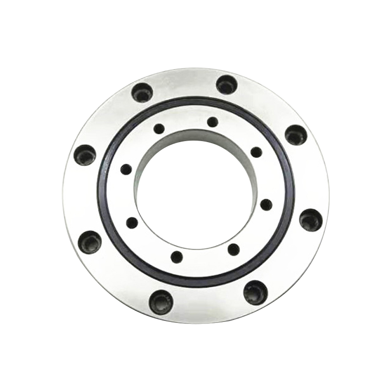
Crossed Cylindrical Roller Bearings
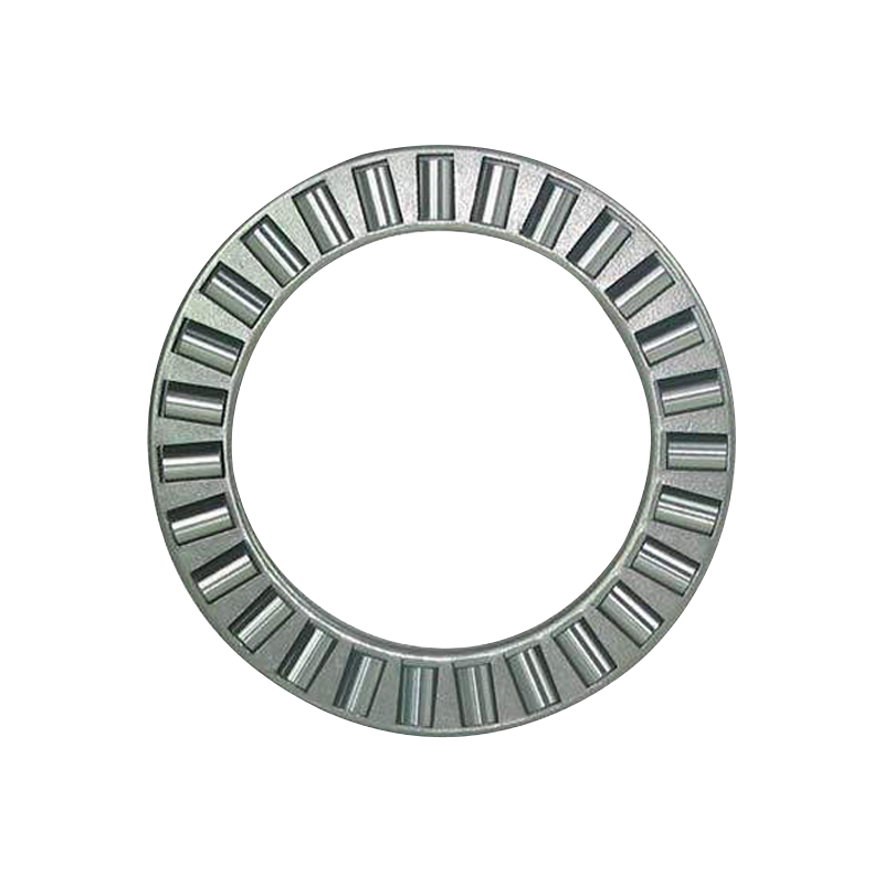
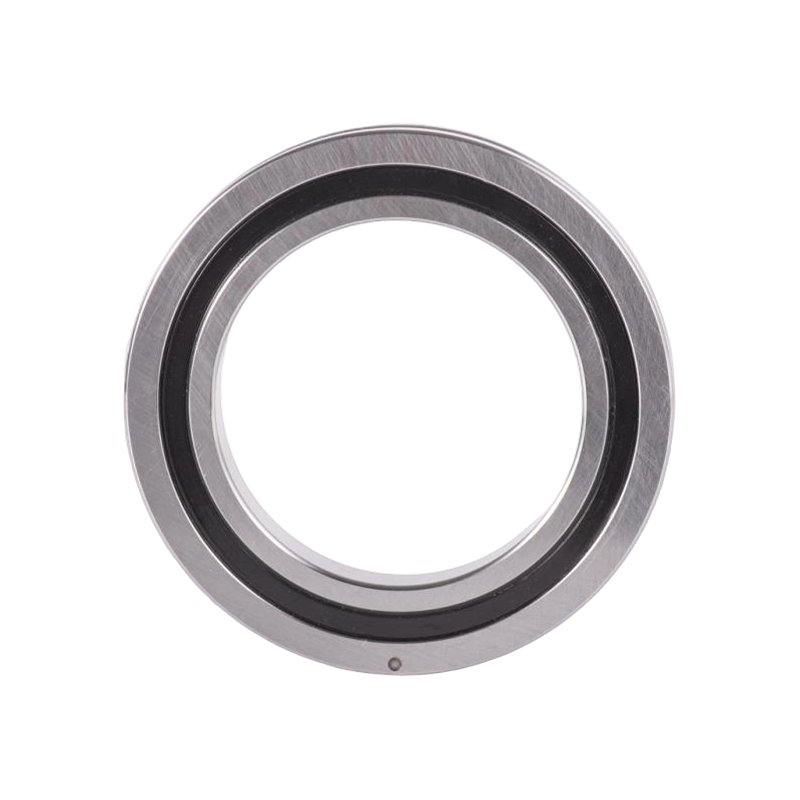
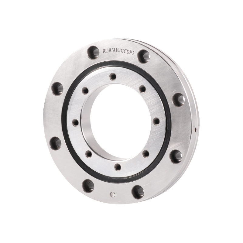
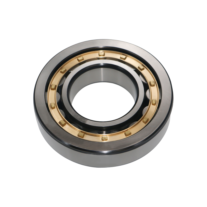
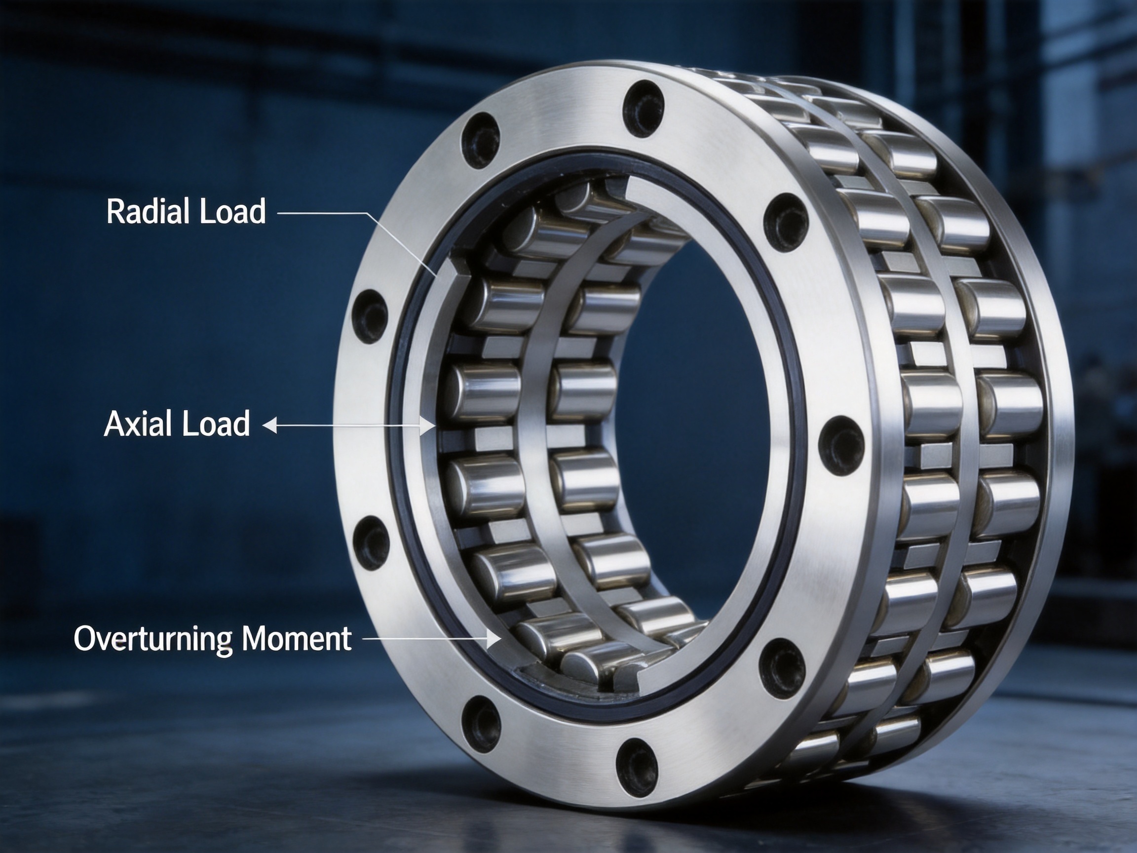
A crossed cylindrical roller bearing consists principally of an outer ring, an inner ring, cylindrical rollers, and spacers or separators. The rollers are positioned between the inner and outer rings, with adjacent rollers arranged in alternating directions. One roller carries load in one direction, while the next roller is oriented to carry load in the direction perpendicular to it.
This crossed arrangement distributes forces over a large number of line contacts. Compared with point-contact rolling elements, cylindrical rollers can provide high load capacity and increased stiffness within a relatively small radial section. Because the rollers are arranged in two directions around the circumference, the bearing can accommodate loads acting along different axes at the same time.
The spacers located between the rollers serve an important purpose. They help prevent direct contact between neighboring rollers, reduce sliding and mutual friction, maintain roller separation, and support smoother rotation. Proper separator geometry also helps the rolling elements remain evenly distributed during operation. This is especially valuable in precision mechanisms that require low torque variation and stable motion.
Crossed cylindrical roller bearings are commonly manufactured with a separable or non-separable structure depending on the series and application. Some designs are supplied with an integrated inner or outer ring, while others are configured to simplify installation and preload adjustment. The correct structural style depends on housing design, shaft arrangement, required rigidity, installation sequence, and the desired accuracy class.
In a conventional radial ball bearing, the rolling elements make point contact with the raceways. Ball bearings are efficient and suitable for high-speed operation, but their contact area is relatively small. A crossed cylindrical roller bearing uses line contact between the cylindrical rollers and raceways. This larger contact area can provide greater load-carrying ability and improved resistance to deformation when the bearing is correctly selected and mounted.
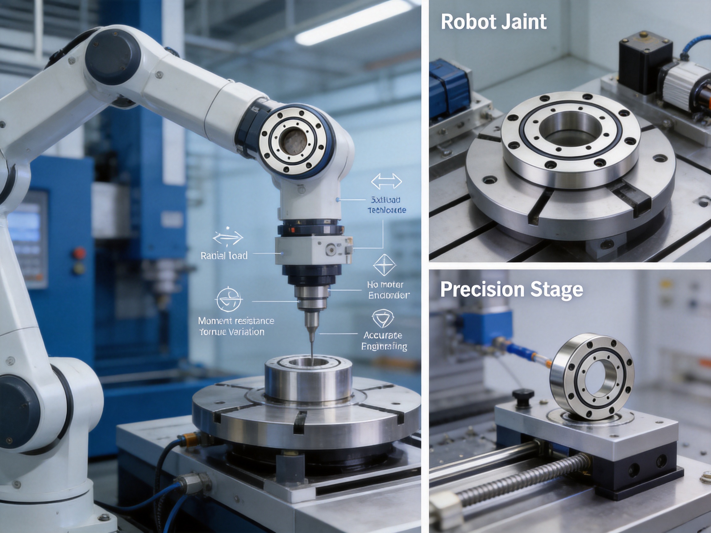
The alternating roller orientation allows the bearing to support radial and axial forces without necessarily requiring two separate bearing arrangements. It can also resist moment loads caused by a force acting at a distance from the bearing center. This capability is one of the main reasons crossed roller bearings are widely used in robot joints, rotary tables, indexing mechanisms, and precision positioning equipment.
Moment rigidity is particularly important in equipment with an extended arm, eccentric load, or offset tooling. If a load is applied away from the rotational center, it creates an overturning moment. Excessive deflection under this moment can cause positioning error, vibration, uneven wear, or interference with adjacent components. A properly sized crossed cylindrical roller bearing helps maintain the relative position of the inner and outer rings under these conditions.
The bearing’s performance depends on more than its basic load rating. Raceway accuracy, roller diameter variation, internal clearance, preload, mounting surface flatness, housing stiffness, lubrication, speed, temperature, and contamination control all influence operating behavior. For this reason, bearing selection should consider the complete mechanical system rather than only the shaft diameter or static load.
The crossed roller design can support several load directions in one bearing. This can reduce the need for separate radial and axial bearing arrangements, simplify the surrounding mechanism, and save axial or radial space. A more compact bearing arrangement may also reduce the weight and inertia of a moving assembly.
Compact construction is particularly advantageous in robotic joints, rotary actuators, camera platforms, inspection systems, and semiconductor handling equipment. In these applications, the available installation envelope is often strictly limited. A bearing that combines radial, axial, and moment-load capability can enable a slimmer machine design.
Line contact between cylindrical rollers and raceways provides a relatively large load-supporting area. When the bearing is mounted in a sufficiently rigid housing and operated with appropriate preload, it can resist elastic deformation and maintain precise movement. High rigidity supports better positioning accuracy and reduces deflection during acceleration, braking, and changes in payload.
High rigidity is especially valuable in machine-tool rotary axes, robot arms, indexing tables, and measurement platforms. The bearing must not only rotate; it must maintain the geometric relationship between the moving and stationary structures while forces change.
The crossed roller arrangement is designed to handle radial load, axial load, and moment load. This feature can simplify bearing layouts and reduce the number of components required in a mechanism. Fewer components may mean fewer tolerance stack-up issues, reduced assembly time, and a smaller overall package.
The load ratings listed for the supplied range include dynamic basic load rating and static basic load rating. Dynamic rating is used in life calculations for rolling contact fatigue, while static rating is relevant when the bearing is exposed to high stationary loads, shock loads, or limited rotation. These values must be interpreted together with the actual load spectrum and the manufacturer’s application guidance.
Separators between the rollers prevent direct roller-to-roller contact and help maintain an orderly rolling arrangement. With accurate raceways, controlled roller geometry, suitable lubrication, and correct preload, the bearing can provide smooth rotation and low torque fluctuation.
Low torque variation improves servo control and can help a motor respond more consistently to small commands. This is important in robotic joints, optical positioning systems, scanning mechanisms, and precision inspection equipment, where small motion errors can affect product quality.
A crossed cylindrical roller bearing can contribute to accurate angular positioning because it combines high rigidity with controlled radial and axial movement. The bearing itself does not replace a precision encoder or a properly designed control system, but it provides a stable mechanical foundation for those systems.
Dimensional accuracy, raceway geometry, preload control, and mounting accuracy all influence the final positioning result. For demanding applications, customers should specify required accuracy, runout, stiffness, preload, lubrication, sealing, and environmental conditions during the quotation and engineering review stage.
The product data includes compact models with bore diameters beginning at approximately 20 mm as well as large models with bore diameters extending beyond 1,000 mm. This range allows crossed roller bearing technology to be applied to small precision mechanisms and large industrial rotary structures.
The catalogue includes series identified by designations such as XRB, XRA, XRBS, XRBC, XRBH, and XRE. These designations represent different product configurations or application variants. Since naming conventions can vary by manufacturer, customers should confirm dimensions, internal design, preload, accuracy, and interchangeability before substituting one series for another.
The following table presents selected models from the supplied product information. It is intended for preliminary comparison. The complete technical selection should be confirmed against the latest production drawing, bearing configuration, tolerance class, lubrication specification, and application conditions.
| Series | Bearing Number | Bore d (mm) | Outside Diameter D (mm) | Width B (mm) | Dynamic Rating C (kN) | Static Rating C0 (kN) | Mass (kg) |
|---|---|---|---|---|---|---|---|
| XRB | XRB2008 | 20 | 36 | 8 | 3.23 | 3.10 | 0.04 |
| XRB | XRB5013 | 50 | 80 | 13 | 16.70 | 20.90 | 0.27 |
| XRB | XRB10020 | 100 | 150 | 20 | 33.10 | 50.90 | 1.45 |
| XRB | XRB15030 | 150 | 230 | 30 | 100.00 | 156.00 | 5.30 |
| XRB | XRB25040 | 250 | 355 | 40 | 195.00 | 348.00 | 14.80 |
| XRB | XRB40040 | 400 | 510 | 40 | 241.00 | 531.00 | 23.50 |
| XRB | XRB600120 | 600 | 870 | 120 | 1490.00 | 2800.00 | 274.00 |
| XRB | XRB1000111 | 1000 | 1250 | 110 | 1220.00 | 3220.00 | 360.00 |
| XRA | XRA5008 | 50 | 66 | 8 | 5.10 | 7.19 | 0.08 |
| XRA | XRA10008 | 100 | 116 | 8 | 7.15 | 13.90 | 0.15 |
| XRA | XRA16013 | 160 | 186 | 13 | 23.30 | 44.90 | 0.59 |
| XRBH | XRBH10020 | 100 | 150 | 20 | 50.90 | 72.20 | 1.45 |
| XRC | XRC20024 | 200 | 250 | 24 | 68.00 | 208.00 | 3.10 |
| XRE | XRE30040 | 300 | 405 | 40 | 212.00 | 409.00 | 17.20 |
Some catalogue entries contain values that should be reviewed carefully before engineering release. For example, certain rows show unusual dimensional or rating relationships, and one large-bearing entry appears to have an outside diameter that may require confirmation. Such discrepancies can result from transcription, product-family differences, or catalogue formatting. UKL’s engineering team should therefore verify the exact part number and drawing before production, particularly for large or custom bearings.
The XRB series covers a broad range of crossed cylindrical roller bearings, from small compact units to very large bearings for industrial machinery. The supplied data includes models with widths ranging from 8 mm to 150 mm and bore diameters from approximately 20 mm to 1,250 mm.
This series is suitable for applications requiring a balance of radial compactness, high rigidity, and multi-directional load support. Depending on size, the series may be used in robot reducers, rotary tables, machine-tool axes, material-handling systems, inspection equipment, and large industrial positioning platforms.
The XRA models listed in the supplied data have relatively narrow widths and are available in bore sizes from approximately 50 mm to 200 mm. Their compact cross-section can be advantageous where axial space is restricted. XRA models are available with and without a “C” suffix in the product information, so the exact meaning of the suffix should be confirmed through the relevant technical drawing and specification sheet.
XRBS models cover sizes from approximately 50 mm to 200 mm in the supplied table. These models share several dimensional and rating values with the XRA group, but the different designation indicates a separate configuration or manufacturing variant. Substitution should not be made solely on the basis of matching dimensions. Internal geometry, mounting method, preload, accuracy, and allowable operating conditions must also be checked.
The XRBC series includes medium and large sizes, with the supplied information ranging from 150 mm bore to approximately 800 mm bore. These bearings can be considered for heavy-duty rotary structures where the combination of moment resistance and large load capacity is important.
XRBH and XRE models provide additional options for designers seeking a particular balance of load capacity, stiffness, geometry, and application suitability. The XRBH data includes compact models from 20 mm bore upward, while the XRE group includes both small and large sizes.
Because series suffixes and prefixes can have manufacturer-specific meanings, a technical inquiry should include the application, load directions, operating speed, temperature, mounting orientation, lubrication, desired accuracy, and available installation space. This information enables the manufacturer to recommend an appropriate configuration rather than simply supplying a nominally similar bearing.
A conventional machine may use separate radial and axial bearings to handle combined loads. Such an arrangement can work effectively, but it may require more components, a longer shaft, additional spacers, and more complicated preload adjustment. A crossed cylindrical roller bearing can often combine these functions in one compact unit.
The reduction in component count can simplify assembly and reduce the number of interfaces where dimensional errors may accumulate. It can also reduce the amount of space required inside the housing. However, the bearing must be correctly sized and mounted, and the structure surrounding it must be sufficiently rigid to realize its potential advantages.
Ball bearings are often preferred for high-speed operation and low friction, but a small ball bearing may not provide the same moment rigidity as a properly preloaded crossed roller bearing of similar envelope size. In applications with an offset load, the crossed roller design can offer a more stable support arrangement.
This does not mean that crossed roller bearings are universally superior. The best choice depends on speed, load, friction, temperature, contamination, cost, life, and accuracy requirements. Crossed roller bearings are especially attractive when stiffness, compactness, and angular accuracy are more important than achieving the highest possible rotational speed.
A compact bearing arrangement can reduce machine size and moving mass. Lower moving mass may improve acceleration response and reduce motor requirements in robotic or servo-driven systems. A shorter load path can also improve system stiffness by reducing the distance between the load and the supporting structure.
In many applications, radial, axial, and moment loads are present simultaneously. A crossed roller bearing is designed around this reality. The crossed roller geometry distributes loads through alternating rolling elements instead of relying on a single load direction.
When properly lubricated and mounted, this can support smooth movement under changing load conditions. It can be particularly beneficial in mechanisms that repeatedly accelerate, decelerate, reverse, or move through a limited angular range.
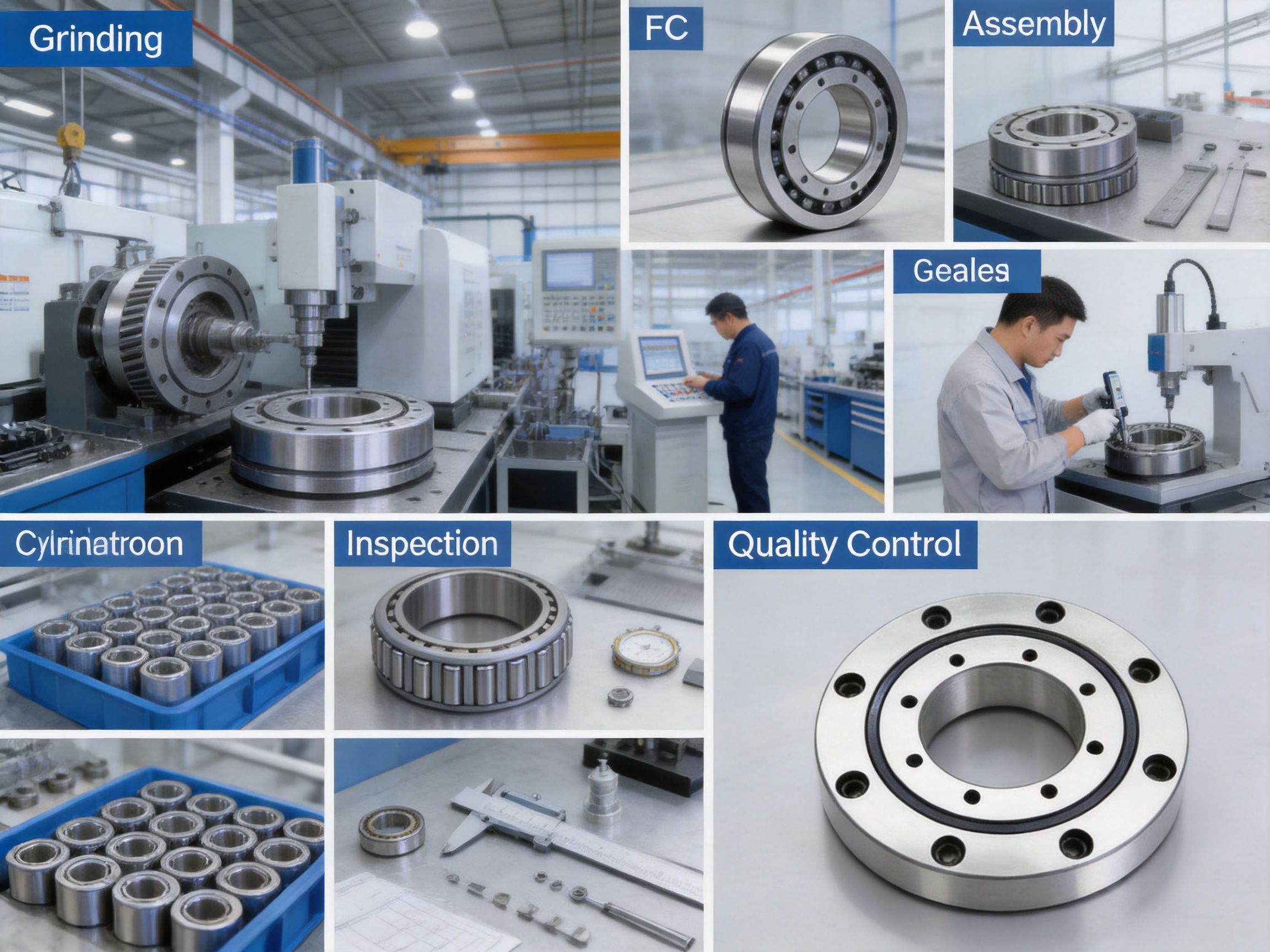
The performance of a precision bearing begins with the quality of its raw material and continues through every production stage. UKL’s manufacturing structure includes forging, turning, heat treatment, grinding, assembly, and packaging. Integrating these stages gives the manufacturer greater opportunity to control the relationship between material properties, geometry, surface finish, and final bearing performance.
Forging shapes the bearing rings before precision machining. A controlled forging process can produce a favorable material flow, reduce unnecessary machining allowance, and support efficient use of steel. The quality of the forged blank influences subsequent turning, heat treatment, and grinding operations.
Material traceability is important at this stage. The steel grade, heat number, chemical composition, cleanliness, and initial condition should be recorded and controlled. For applications involving high loads, shock, continuous operation, or safety-related motion, traceability supports more reliable quality management.
Turning establishes the basic dimensions and reference surfaces of the inner and outer rings. Accurate turning reduces the amount of material that must be removed during grinding and creates stable datum surfaces for later operations.
At this stage, control of concentricity, face runout, shoulder geometry, groove location, and machining allowance is essential. Errors introduced during rough or semi-finish machining can become difficult to correct later. Modern production control therefore combines process parameters, inspection records, and equipment maintenance to maintain repeatability.
Heat treatment gives the bearing rings the hardness, strength, wear resistance, and dimensional stability required for rolling contact. The process may include heating, quenching, tempering, and controlled cooling according to the selected material and design requirements.
Heat treatment must be carefully controlled because excessive distortion can affect raceway geometry and final clearance. Hardness distribution, case depth where applicable, retained austenite, distortion, and metallurgical structure all influence bearing life. A strong heat-treatment process helps ensure that the rings retain their performance under repeated rolling contact.
Grinding is one of the most important stages in crossed cylindrical roller bearing production. The raceways must provide accurate geometry and a smooth surface to support consistent rolling contact. Grinding also establishes final dimensions, runout, roundness, and raceway alignment.
Precision grinding requires controlled wheel condition, coolant management, machine stability, dressing intervals, and in-process measurement. Grinding burn, excessive residual stress, waviness, or poor surface finish can reduce fatigue life and increase operating torque. For this reason, raceway inspection is a central part of bearing quality control.
The rollers must be manufactured with controlled diameter, length, straightness, end geometry, hardness, and surface finish. Even small differences in roller size can affect load distribution and preload. Roller sorting and matching help create a more uniform internal assembly.
The crossed arrangement also requires correct orientation. Rollers must be placed alternately according to the intended load directions, with suitable separators positioned between them. Accurate assembly is essential because a roller that is incorrectly oriented or improperly seated can affect rotation, torque, and load sharing.
Assembly combines the rings, rollers, spacers, seals or protective elements where applicable, and lubrication. Cleanliness is especially important. Fine particles, metal chips, abrasive residue, or moisture can damage raceways and cause premature wear.
Preload is another critical parameter. An appropriate preload can improve rigidity, reduce internal movement, and enhance positioning accuracy. Excessive preload, however, can increase friction, operating temperature, torque, and wear. Insufficient preload may allow unwanted clearance, vibration, and loss of stiffness.
UKL’s integrated production and assembly capabilities support the adjustment and inspection of these factors before shipment. For custom applications, preload and accuracy requirements should be agreed in advance because they influence bearing selection, mounting method, lubrication, and inspection criteria.
Final inspection may include dimensional measurement, radial and axial runout checks, rotational torque testing, visual inspection, noise or vibration evaluation, hardness verification, and packaging inspection. The exact inspection plan depends on the bearing type, size, accuracy class, and customer requirements.
Packaging must protect the bearing from corrosion, impact, contamination, and humidity during storage and transportation. Large bearings require particular attention to lifting, support, wrapping, and crate design. Clear identification of bearing number, batch, production date, and inspection status supports traceability throughout the customer’s supply chain.
Robot joints often require high stiffness, compact dimensions, low torque variation, and resistance to moment loads. The arm or wrist may carry a payload that is offset from the joint center, creating a significant overturning moment. A crossed cylindrical roller bearing can support the joint structure while preserving angular accuracy and reducing the need for multiple bearing sets.
In robot applications, bearing selection should account for acceleration, deceleration, oscillatory motion, emergency stops, duty cycle, payload variation, reducer arrangement, and environmental contamination. Lubrication compatibility with the reducer or actuator is also important.
Rotary tables, indexing systems, tool changers, and precision feed mechanisms require stable support under cutting forces and changing loads. Bearing rigidity influences table deflection and the accuracy of the machining process. Crossed roller bearings can be used where compactness and moment resistance are needed.
Machine-tool designers must also consider thermal expansion. Heat generated by preload, motor losses, nearby cutting operations, or coolant can change internal conditions. Bearing fits, housing materials, lubrication, and preload should be selected with the expected temperature range in mind.
Wafer handling, inspection stages, alignment platforms, and assembly equipment require clean, accurate, and repeatable motion. Small errors in runout or torque can affect positioning and throughput. Depending on the environment, the bearing may require special grease, low-particle operation, protective seals, or a cleanroom-compatible configuration.
Optical instruments, scanning systems, antenna positioning units, and coordinate measuring equipment rely on controlled movement. High stiffness helps prevent deflection, while low torque variation supports smooth servo control. A carefully selected crossed roller bearing can provide a stable rotary interface in these applications.
Rotary tables must support workpieces, fixtures, tooling, and dynamic loads while maintaining repeatable angular positions. The bearing may experience continuous rotation, intermittent indexing, dwell periods, and rapid reversals. Static load rating and moment rating are important during dwell and clamping, while dynamic rating and lubrication are important during repeated motion.
Automated assembly machines, packaging equipment, welding systems, material-handling devices, and inspection stations often combine high cycle rates with limited installation space. A crossed roller bearing can help simplify the rotary mechanism and support the load generated by tooling or offset components.
Determine the radial load, axial load, and overturning moment. Loads should be evaluated under normal operation, acceleration, braking, emergency stop, impact, clamping, and maintenance conditions. If the load varies over time, create a load spectrum rather than relying only on the maximum or average value.
Check shaft diameter, housing bore, available radial space, available axial width, shoulder dimensions, mounting surfaces, and adjacent components. The bearing outside diameter and width must be compatible with the housing design. Large crossed roller bearings may require special lifting and installation arrangements.
The supplied table lists reference speed and limiting speed as unavailable or marked with dashes for the presented models. Therefore, operating speed must be confirmed directly with the manufacturer. Continuous rotation, oscillation, indexing, and frequent reversals impose different demands on lubrication and internal motion.
Speed is influenced by bearing size, preload, lubricant, temperature, cage or spacer design, load, and mounting accuracy. A bearing suitable for slow, high-load indexing may not be suitable for continuous high-speed rotation.
Specify the allowable deflection, runout, positioning error, repeatability, and stiffness. If a bearing is used in a servo axis, the mechanical accuracy should be coordinated with encoder resolution, reducer backlash, drive tuning, and structural rigidity.
Preload improves rigidity and can reduce internal movement, but it also increases torque and heat. The correct value depends on the application. Light preload may be appropriate for smooth movement, while higher preload may be necessary for precision positioning or moment resistance.
Evaluate temperature, dust, water, cutting fluid, corrosive chemicals, vacuum, radiation, vibration, shock, and cleanroom requirements. Sealing and lubrication must be compatible with the environment. In contaminated environments, effective protection may be more important than achieving the lowest possible friction.
Lubrication reduces friction, limits wear, carries away heat, and protects the rolling contacts. Grease is commonly used in many industrial applications because it is easy to retain, but oil or special lubricants may be preferred for high-speed, high-temperature, vacuum, or clean applications.
The lubricant quantity should be controlled carefully. Too little lubricant can cause wear and overheating, while too much can increase churning losses and temperature. Relubrication intervals depend on speed, load, temperature, contamination, and operating cycle.
Proper installation is essential to achieving the expected performance of a crossed cylindrical roller bearing. The shaft, housing, shoulders, and mounting surfaces must be clean and free from burrs. Dirt or raised metal at the seating surfaces can distort the bearing rings after installation.
Mounting surfaces should be checked for flatness, perpendicularity, roundness, and surface finish. A housing that is not sufficiently rigid or accurately machined may impose unwanted deformation on the bearing. This can increase torque, reduce load distribution, and affect accuracy.
During assembly, force should be applied only to the ring being fitted. Applying installation force through the rollers can damage raceways and separators. Large bearings should be lifted with suitable equipment to prevent distortion or accidental impact.
Fasteners should be tightened in a gradual, crosswise sequence using the specified torque. For precision structures, the tightening sequence can affect runout and preload. After installation, the bearing should be rotated slowly by hand or at low speed to verify smooth movement before full operation.
Maintenance should include monitoring of noise, vibration, torque, temperature, runout, and backlash or movement. A change in any of these parameters may indicate contamination, lubricant deterioration, mounting looseness, raceway damage, or excessive preload.
Storage conditions also influence bearing life. Bearings should remain sealed in their original packaging until installation. Storage areas should be dry, clean, and protected from extreme temperature changes. Large bearings should be supported in a manner that avoids permanent deformation.
UKL Bearing Manufacturing Co., Ltd. operates as an integrated bearing manufacturer and trader with experience in OEM and ODM export markets. The company reports a workforce of 201 to 500 employees and production capacity of approximately 10,000 to 50,000 units per month. This scale supports both standard product supply and customized engineering programs.
The company’s production coverage includes forging, turning, heat treatment, grinding, assembly, and packaging. By coordinating these processes internally, UKL can improve production scheduling, maintain process traceability, and respond more efficiently to customer-specific requirements.
UKL also maintains research and development capabilities focused on high-precision cross roller bearings, dual-direction thrust angular contact ball bearings, and other bearing products for CNC machinery, robotics, and intelligent automation. This product knowledge enables the company to discuss the bearing as part of a machine system rather than as an isolated catalogue item.
International distribution experience supports customers in Europe, Asia, Africa, Russia, North America, and other markets. The company identifies export destinations including the United States, Italy, Germany, Poland, South Africa, Egypt, and India. Its multilingual service team provides technical response, installation guidance, and after-sales support for global customers.
For OEM and ODM customers, important advantages include communication during product development, drawing review, prototype coordination, production planning, quality documentation, and repeat-order management. A customized bearing may involve changes to dimensions, preload, accuracy, lubrication, sealing, material, mounting holes, flange structure, or corrosion protection.
UKL also states that it adopts environmentally responsible processes, promotes material recycling, and works to optimize energy usage. These practices are increasingly relevant to industrial customers that evaluate not only product performance but also supply-chain responsibility and long-term manufacturing stability.
Standard bearings are appropriate for many applications, but specialized equipment may require a customized solution. Crossed cylindrical roller bearings can be adapted in several ways, subject to engineering feasibility and production requirements.
Potential customization areas include bore and outside diameter, bearing width, mounting holes, flange arrangement, ring split design, preload, accuracy class, material, surface treatment, lubrication, seals, corrosion protection, and packaging. Large-diameter bearings may also require special transport supports or installation documentation.
Customers seeking a quotation should provide a technical specification whenever possible. Useful information includes the target bearing number or dimensions, load conditions, speed, rotation pattern, duty cycle, temperature, environment, mounting orientation, required life, allowable torque, accuracy, preload, lubricant, annual quantity, and delivery requirements.
When a drawing is not available, UKL can evaluate the application based on a mechanical description and operating data. A technical review may identify whether a standard model is suitable or whether an alternative series, modified geometry, or custom configuration is preferable.
Prototype testing is recommended for new or high-risk applications. Testing may include torque measurement, temperature rise, runout, stiffness, noise, vibration, endurance, and load cycling. Results from the prototype phase can be used to refine preload, lubrication, sealing, and mounting details before mass production.
The purchase price of a bearing is only one part of its total cost. A bearing that provides high rigidity and multi-directional load support may reduce the need for additional components, shorten assembly time, and simplify maintenance. Improved positioning accuracy may also reduce scrap, rework, calibration, and downtime.
At the same time, crossed cylindrical roller bearings require careful mounting and lubrication. If the application does not need high moment rigidity or multi-directional load capacity, a conventional ball bearing may offer a more economical solution. Product selection should therefore be based on total system value rather than the lowest unit price.
Manufacturing consistency is also a cost factor. Variations in raceway geometry, preload, cleanliness, or dimensional accuracy can create assembly problems and early failures. A supplier with integrated process control and documented inspection can reduce these risks, especially for OEM customers purchasing repeated batches.
The main advantage is its ability to support radial loads, axial loads, and overturning moments in a compact bearing arrangement. Alternating cylindrical rollers provide line contact and can deliver high rigidity and load capacity when the bearing is correctly selected and mounted.
The rollers are arranged alternately at right angles around the bearing. This crossed orientation allows different groups of rollers to support loads acting in different directions.
Spacers help prevent adjacent rollers from rubbing directly against each other. They maintain separation, support orderly roller movement, reduce friction, and help promote smooth rotation.
They can be used in rotating applications, but allowable speed depends on bearing size, preload, lubrication, load, temperature, and design configuration. The supplied product table does not provide speed ratings for the listed models, so the permissible operating speed should be confirmed with the manufacturer.
Yes. Their internal roller arrangement is designed to resist overturning moments as well as radial and axial loads. The actual allowable moment depends on bearing size, preload, mounting rigidity, load position, and operating conditions.
The basic dynamic load rating is used when estimating rolling-contact fatigue life under repeated movement. The basic static load rating is used to evaluate permanent deformation risk when the bearing is stationary, moving slowly, subjected to shock, or exposed to a high peak load.
In some designs, one crossed roller bearing can perform functions that would otherwise require separate radial and axial bearings. However, replacement must be evaluated using load, stiffness, accuracy, speed, life, mounting, and environmental requirements. Dimensional similarity alone is not sufficient.
Use a lubricant compatible with the bearing materials, seals, speed, temperature, and surrounding equipment. The correct amount is important because both insufficient and excessive lubrication can cause problems. Lubrication details should be confirmed with UKL for the selected model and application.
UKL provides OEM and ODM manufacturing support and can review customized requirements such as dimensions, preload, accuracy, mounting features, lubrication, sealing, and packaging. A technical drawing or complete application specification should be provided for evaluation.
Important information includes bore and outside diameter, width, radial load, axial load, moment load, speed, duty cycle, temperature, environment, required accuracy, stiffness, preload, lubrication, installation method, expected service life, and annual quantity.
Product series can include different internal configurations, and catalogue data may contain formatting or transcription errors. Confirming the bearing number, dimensions, load ratings, speed limits, preload, and drawing helps prevent an unsuitable selection, particularly for large or customized bearings.
Crossed cylindrical roller bearings provide a practical solution for precision rotary mechanisms that require compact construction, high rigidity, multi-directional load support, and stable positioning. Their alternating cylindrical rollers create a bearing arrangement capable of handling radial forces, axial forces, and overturning moments in a single component.
The supplied product range includes compact models for precision mechanisms and large models for industrial rotary equipment. Multiple series and configurations provide flexibility for robotics, CNC machinery, rotary tables, inspection systems, semiconductor equipment, optical instruments, and automated production lines.
The performance of a crossed roller bearing depends on the complete engineering system. Correct load calculation, dimensional selection, preload, lubrication, mounting accuracy, housing stiffness, contamination control, and maintenance are all essential. Customers should verify the final technical data and production drawing before release, especially where catalogue entries require clarification.
UKL Bearing Manufacturing Co., Ltd. supports these applications through integrated manufacturing processes covering forging, turning, heat treatment, grinding, assembly, and packaging. Its R&D capabilities, OEM/ODM experience, export infrastructure, production capacity, and technical service help customers develop bearing solutions for both standard and specialized equipment.
For organizations seeking a compact and rigid bearing solution, a detailed technical discussion with the manufacturer is the best starting point. By matching the bearing series to the actual mechanical loads and operating environment, designers can achieve better reliability, longer service life, lower maintenance requirements, and more consistent machine performance.
1. UKL Bearing Manufacturing Co., Ltd., Crossed Cylindrical Roller Bearings Product Information and Dimensional Data.
2. ISO 76, Rolling Bearings — Static Load Ratings.
3. ISO 281, Rolling Bearings — Dynamic Load Ratings and Rating Life.
4. ISO 199, Rolling Bearings — Thrust Bearings — Geometrical Product Specifications and Nominal Dimensions.
5. General engineering principles for rolling-bearing selection, mounting, lubrication, and maintenance.
6. Industrial automation and precision machinery design practices for rotary bearing arrangements.
Product Categories
Contact Us

Jane@ukl-bearing.com
Jenny@ukl-bearing.com
Andy@ukl-bearing.com
Ivy@ukl-bearing.com

+86-510- 88763239
+86-15371057968

No.1 Hehuan Road, Hudai Town, Binhu District, Wuxi City.
Ready to Begin?
Get in Touch

Now!
UKL BEARING
 English
 Español
 русский