Content
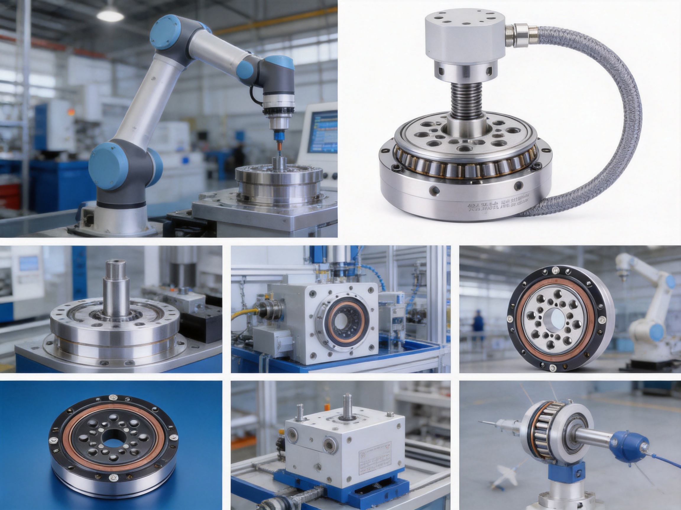
Harmonic reducers are essential transmission components in modern robotics, machine tools, aerospace equipment, medical automation, semiconductor machinery, and other applications that demand compact construction and precise motion control. Within a harmonic reducer, the bearing system plays a critical role in maintaining rigidity, guiding elastic deformation, supporting external loads, and preserving rotational accuracy during continuous operation. A bearing that is insufficiently rigid, poorly preloaded, or dimensionally inconsistent can affect the accuracy of the entire reducer.
Precision harmonic reducer bearings are developed specifically for these demanding operating conditions. They combine high geometric accuracy, controlled internal clearance or preload, compact dimensions, dependable load support, and stable rotation. The product range described in this article is intended for harmonic reducer configurations using rigid crossed roller bearings and flexible thin-walled bearing arrangements. It is available in multiple sizes, allowing designers to select a bearing according to reducer capacity, output diameter, installation space, and expected operating load.
UKL Bearing Manufacturing Co., Ltd. supplies precision bearing solutions for robotics, automation, CNC equipment, and other industrial applications. The company integrates bearing research and development, production, quality management, and international distribution. Its manufacturing capabilities cover forging, turning, heat treatment, grinding, assembly, inspection, and packaging, providing a coordinated production route for custom and standard bearing requirements.
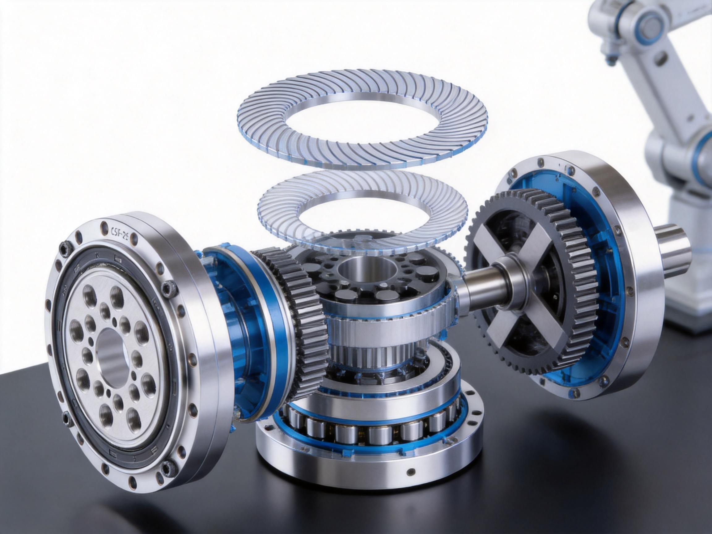
A harmonic reducer generally includes three principal mechanical elements: the harmonic generator, the flexure, and the rigid wheel. The harmonic generator creates controlled elliptical movement. The flexure is a thin-walled, elastic component that deforms during operation. The rigid wheel contains internal teeth that engage with the external teeth of the flexure. Because the rigid wheel has more teeth than the flexure, their relative movement produces a high reduction ratio in a compact package.
The bearing system supports this mechanism and allows the components to move in a controlled and repeatable manner. A rigid bearing is commonly installed at the output end of the reducer. In many designs, this rigid bearing is a crossed roller bearing capable of carrying radial loads, axial loads, and overturning moments. Its function is not limited to simple rotation. It also supports the external connection and helps maintain the positional relationship between the reducer and the driven mechanism.
A flexible bearing is commonly installed around the elliptical cam of the harmonic generator. This bearing is usually a thin-walled deep groove ball bearing. As the cam rotates, the outer ring of the flexible bearing undergoes elastic deformation. The bearing must accommodate repeated deformation without premature fatigue, excessive friction, or unstable rotation. The maximum permissible radial deformation is therefore one of the most important performance parameters for the flexible bearing.
The rigid and flexible bearings operate under different mechanical conditions. The rigid bearing emphasizes rigidity, moment capacity, rotational accuracy, and installation stability. The flexible bearing emphasizes elastic compliance, fatigue resistance, dimensional consistency, and the ability to maintain smooth rolling contact during repeated elliptical deformation. A successful harmonic reducer bearing solution must address both sets of requirements.
In the harmonic reducer assembly, the inner bore of the flexible bearing fits over an elliptical cam. When the cam rotates, the bearing follows the elliptical profile. The outer ring expands and contracts in two principal directions as it rolls along the cam surface. The resulting deformation enables the flexure to engage with the rigid wheel at the long axis of the ellipse and disengage at the short axis.
The flexure is connected to the output side of the reducer, while the rigid bearing is mounted at the output end to create an accurate interface for external equipment. During operation, the bearing system must maintain controlled contact between the moving elements despite changing load direction, repeated deformation, and high reduction ratios.
Precision in the bearing geometry is essential because even a small deviation in raceway roundness, ring thickness, roller diameter, or mounting surface flatness can influence reducer backlash, torque fluctuation, noise, and service life. For this reason, harmonic reducer bearings require stricter manufacturing and assembly controls than many conventional bearing applications.
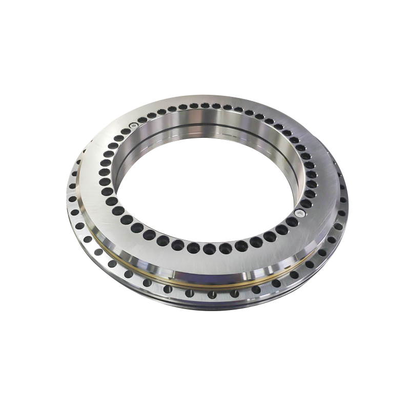
Crossed roller bearings are particularly suitable for the rigid bearing position because their rollers are arranged alternately at right angles. This arrangement allows the bearing to handle loads from several directions using a compact cross section. Compared with a conventional radial ball bearing of similar outer dimensions, a crossed roller bearing can provide strong resistance to overturning moments and improved positional stability for an output flange or robot joint.
The flexible bearing requires a different design approach. Its thin-walled rings and rolling elements must tolerate deformation while maintaining contact with the cam and flexure. The bearing must not be excessively rigid in the radial direction, but it must still provide predictable rolling behavior. Manufacturing consistency is therefore especially important. Variations in wall thickness, raceway geometry, or internal clearance can create uneven contact and localized stress during operation.
Harmonic reducers are used when the output shaft or flange must move with minimal positional error. Bearing runout, raceway waviness, and mounting distortion can directly influence the final output accuracy. Precision harmonic reducer bearings are manufactured and inspected with attention to dimensional tolerances, rotation quality, and assembly consistency.
Accurate bearing geometry helps the reducer maintain a stable center of rotation. It also reduces the risk that bearing variation will be mistaken for gear-related backlash or transmission error. This is particularly valuable in robotic joints, where small angular deviations may affect the position of an end effector over a large working envelope.
The rigid bearing must support the output assembly as well as external radial, axial, and moment loads. A crossed roller configuration distributes the load over multiple rollers and provides a broad support arrangement. This helps the output flange resist tilting when a robot arm, tool, or workpiece generates an offset load.
High rigidity contributes to better motion repeatability and improved response to servo commands. It also helps reduce deflection under load, which is important in machining equipment and precision assembly systems. Before shipment, preload can be applied according to the specified application so that the bearing provides the required stiffness without producing excessive friction.
Harmonic reducers are often installed inside robotic joints or compact rotary modules. Available space is limited, and designers must balance torque capacity, reducer diameter, motor size, wiring, seals, and bearing dimensions. The product range includes compact models as well as larger sizes for higher load requirements.
The compact structure of a crossed roller bearing allows the designer to achieve high load capacity and moment resistance without using a large conventional bearing arrangement. This can reduce the overall size and weight of the joint, helping robotic equipment achieve lower inertia and faster acceleration.
Preload is an important factor in rigid bearing performance. Proper preload removes unwanted internal movement and increases rigidity. It can also improve rotational accuracy by stabilizing the rolling elements under changing loads. However, excessive preload increases friction, heat generation, and torque requirements.
Precision assembly enables the preload to be controlled within an appropriate range for the application. The suitable value depends on the reducer design, operating speed, expected load, temperature, lubrication, and required service life. UKL can support OEM and ODM projects in which preload, fit, lubrication, sealing, and packaging requirements are defined according to the customer’s equipment.
The flexible bearing is exposed to continuous radial deformation as the elliptical cam rotates. The bearing must maintain smooth rolling contact under this movement while avoiding excessive stress concentration. A carefully controlled bearing structure helps achieve repeatable deformation characteristics across the circumference.
Reliable deformation performance supports stable tooth engagement between the flexure and rigid wheel. It can also help limit torque fluctuation, reduce vibration, and maintain consistent transmission behavior throughout the operating cycle. For flexible bearings, the maximum radial deformation should be evaluated together with the cam profile, bearing clearance, load, speed, lubrication, and temperature.
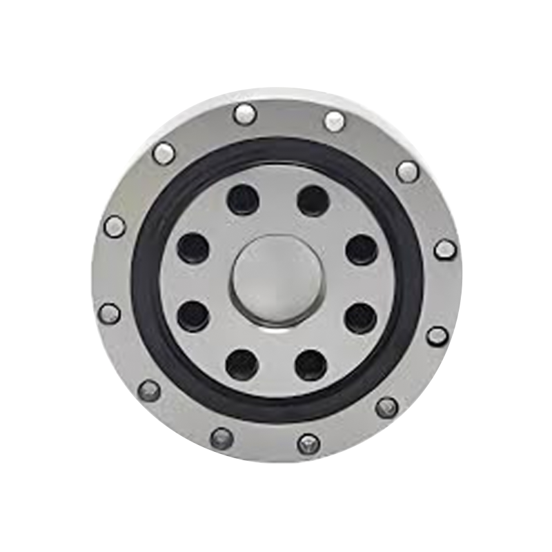
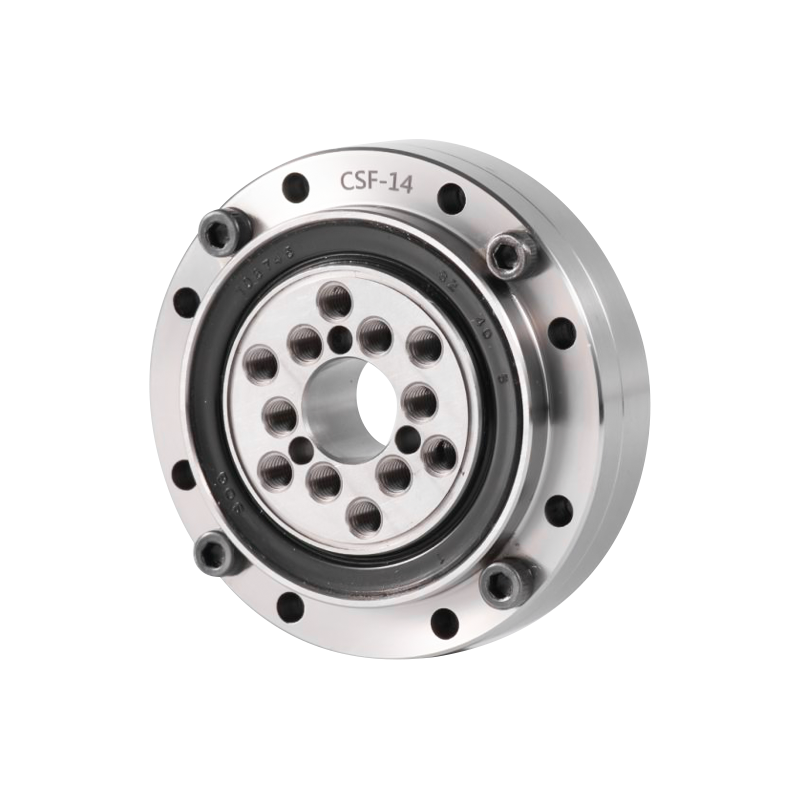
The available CSF(G) series includes sizes from CSF(G)-14 through CSF(G)-65. This range accommodates compact robotic joints, medium-sized automation modules, and larger harmonic reducer assemblies. Designers can select a model according to bore size, outside diameter, mounting pattern, reducer frame size, and load requirements.
Different sizes also provide flexibility when a manufacturer develops a family of robotic joints. Standardized bearing interfaces can simplify product development, spare-parts planning, and maintenance. Where a standard dimension does not meet the required load or installation conditions, custom engineering may be considered.
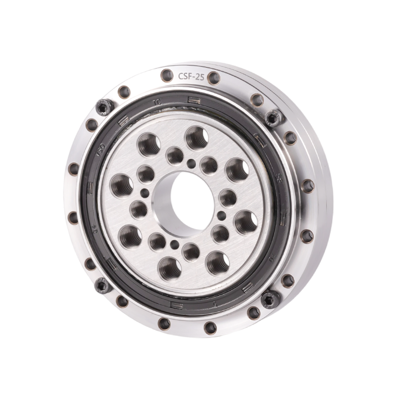
The following table summarizes the principal dimensions and installation information supplied for the precision harmonic reducer bearing series. The dimensions should be confirmed against the latest technical drawing before production use. Installation hole patterns, thread specifications, and dimensional references should be interpreted together with the reducer housing and output flange design.
| Model | D (mm) | d (mm) | C (mm) | H (mm) | B (mm) | dm (mm) | dn (mm) | dl (mm) | Weight (kg) |
|---|---|---|---|---|---|---|---|---|---|
| CSF(G)-14 | 55 | 11 | 16 | 16.5 | 13.5 | 49 | 8-φ3.5 | 23 | 0.15 |
| CSF(G)-17 | 62 | 10 | 16 | 16.5 | 13.5 | 56 | 10-φ3.5 | 27 | 0.24 |
| CSF(G)-20 | 70 | 14 | 16 | 16.5 | 13.5 | 64 | 12-φ3.5 | 32 | 0.30 |
| CSF(G)-25 | 85 | 20 | 18 | 18.5 | 16.5 | 79 | 16-φ3.5 | 42 | 0.45 |
| CSF(G)-32 | 112 | 26 | 21.5 | 22.5 | 19 | 104 | 16-φ4.5 | 55 | 0.90 |
| CSF(G)-40 | 126 | 24/32 | 22.5 | 24 | 21.5 | 117 | 20-φ5 | 68 | 1.30 |
| CSF(G)-50 | 157 | 32/40 | 30 | 31 | 28 | 147 | 16-φ5.5 | 84 | 2.80 |
| CSF(G)-65 | 210 | 44/52 | 37 | 39 | 35 | 198 | 20-φ6.5 | 110 | 7.90 |
The table includes the principal external dimensions and installation-related values provided for the series. The entries shown as two values, such as 24/32 or 32/40, indicate alternative bore dimensions associated with the relevant model configuration. Customers should verify whether a selected version is intended for a specific reducer structure before placing an order.
Installation holes and thread specifications are also important. A bearing may have the correct outside diameter and bore but still be unsuitable if the pitch circle diameter, hole count, clearance-hole diameter, or thread size does not match the mating components. Correct mounting references should therefore be included on drawings and confirmed during sample approval.
Precision Harmonic Reducer Bearing
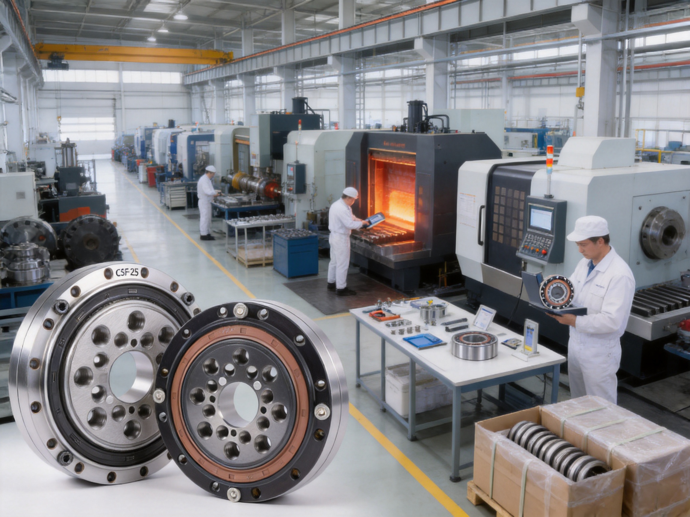
The performance of a harmonic reducer bearing depends on the complete manufacturing chain rather than on one isolated process. UKL Bearing Manufacturing Co., Ltd. integrates multiple production stages, including forging, turning, heat treatment, grinding, assembly, and packaging. Coordinating these operations within one manufacturing system helps reduce process variation and supports traceability from raw material preparation to finished product inspection.
Bearing rings must withstand repeated rolling contact, fluctuating loads, and long operating cycles. The material preparation and forging stages establish the basic grain flow, shape, and structural integrity of the rings. Appropriate control of the forging process can reduce unnecessary material waste and provide a stable foundation for subsequent machining.
At this stage, attention is given to dimensions, surface condition, and material consistency. Forged components are then prepared for machining and heat treatment. The specific material grade and heat-treatment specification should be selected according to load, speed, operating temperature, corrosion conditions, and customer requirements.
Turning produces the initial geometry of the bearing rings, including raceway allowances, shoulder features, mounting surfaces, and locating diameters. The accuracy of turning affects the amount of material available for grinding and helps establish a stable reference for later operations.
For harmonic reducer bearings, special attention is required for thin-walled components. Excessive machining stress or uneven material removal may contribute to deformation. Controlled turning parameters, suitable workholding, and appropriate inspection procedures help maintain the required ring geometry before heat treatment.
Heat treatment gives the bearing material the hardness and structural properties required for rolling contact fatigue resistance. The cycle must be controlled carefully because inadequate treatment can reduce durability, while excessive distortion can make it difficult to achieve final dimensional accuracy.
After heat treatment, components are checked for hardness, deformation, and surface condition. The treatment parameters are selected to support the intended application. Flexible bearing rings require particular attention because thin sections may be more sensitive to dimensional change and residual stress.
Grinding is one of the most important stages in precision bearing production. It establishes the final dimensions and improves the raceway surface. For harmonic reducer bearings, grinding accuracy influences rotation, friction, noise, preload, and contact distribution.
Raceway roundness, profile, waviness, ring width, mounting surfaces, and shoulder geometry must be controlled in accordance with the product specification. Fine surface quality helps create consistent contact between the rolling elements and raceways. It also supports stable lubrication and reduces the likelihood of localized stress.
Where required, additional finishing operations can be applied to improve surface characteristics. The objective is not simply to achieve a smooth appearance, but to create a controlled functional surface that performs consistently under the load and motion conditions of the reducer.
Assembly determines how individual rings, rollers, cages, seals, and lubrication elements function as one bearing unit. Cleanliness is essential because small particles can damage precision raceways or change the effective preload. Components must be handled carefully to prevent impact marks, scratches, or contamination.
For crossed roller bearings, roller orientation and spacing must be controlled correctly. Alternating roller orientation enables the bearing to support loads in multiple directions. Incorrect assembly can reduce load capacity, increase torque, and cause abnormal wear.
Preload is evaluated and adjusted according to the product specification. The assembly process must balance rigidity and smooth operation. Inspection may include starting torque, running torque, rotation quality, axial movement, radial movement, and dimensional verification. For OEM projects, the assembly specification can be aligned with the customer’s reducer housing, shaft fit, and operating profile.
Before shipment, finished bearings are inspected to ensure that they correspond to the required model and configuration. Dimensional checks, visual examination, rotation testing, and packaging verification help reduce the risk of incorrect installation at the customer’s facility.
Packaging protects the bearing from impact, moisture, dust, and corrosion during storage and transportation. Appropriate preservation methods are particularly important for international shipments and for products that may remain in inventory before assembly. Product identification should remain clear so that model, quantity, batch information, and customer-specific requirements can be verified quickly.
Two bearings may have identical nominal dimensions but perform differently in a harmonic reducer. The differences may result from raceway geometry, radial clearance, preload, surface waviness, roller diameter variation, ring deformation, or assembly cleanliness. These factors influence the dynamic behavior of the reducer even when the basic dimensions appear correct.
For a rigid crossed roller bearing, inconsistent preload may cause either excessive movement or unnecessarily high friction. Excessive internal movement can reduce rigidity and lead to output deflection. Excessive preload can increase heat generation and motor power demand. Consistent assembly therefore provides a practical advantage over products that are supplied with limited control of internal performance.
For a flexible bearing, the relationship between the cam and bearing bore is equally important. If the bearing does not deform uniformly around the ellipse, the flexure may experience uneven engagement with the rigid wheel. This can lead to torque variation, vibration, and accelerated wear. Dimensional consistency and controlled internal clearance help the flexible bearing perform predictably.
UKL’s integrated production model supports communication between process engineering, production, inspection, and customer service. This structure is useful when the application requires special preload, non-standard mounting dimensions, customized packaging, or technical documentation for a new reducer platform.
Standard deep groove ball bearings are effective for many radial-load applications, but they may not provide the same moment resistance or structural support as a crossed roller bearing in a robotic joint. A harmonic reducer output flange can be exposed to an overturning moment when the attached arm or tool is offset from the bearing center. A crossed roller arrangement is better suited to supporting this combined loading condition in a compact space.
Standard deep groove bearings may also require multiple bearing rows or a wider spacing arrangement to achieve comparable output stability. That approach can increase the package size and complicate alignment. A precision crossed roller bearing can simplify the mechanical layout by combining multi-directional load support in one bearing structure.
Angular contact ball bearings can provide axial and radial load support, and paired arrangements can resist moments. However, a paired angular contact solution may require more axial space and careful matching between bearing sets. It may also require a more complex adjustment process to achieve the intended preload.
A crossed roller bearing offers an alternative for compact harmonic reducer output structures. Its orthogonal roller arrangement provides high rigidity in a relatively thin section. The most suitable choice depends on speed, moment load, available space, accuracy requirements, and the design of the surrounding components.
Low-cost bearings may appear attractive during initial procurement, but unsuitable variation in clearance, preload, surface finish, or dimensional accuracy can increase the total cost of a reducer project. Problems may emerge during assembly, testing, or field operation, resulting in vibration, noise, reduced positioning accuracy, and service interruptions.
A precision-focused bearing supplier provides value by controlling the factors that affect the complete transmission system. Stable manufacturing, application support, inspection records, and reliable repeatability are often more important than the lowest unit price. For robot manufacturers, consistent bearing behavior also reduces the need to redesign the housing, adjust the gear mesh, or compensate for unpredictable output error.
Robotic joints require compact reducers that can deliver high torque, accurate positioning, and repeatable motion. The rigid bearing supports the output flange, while the flexible bearing enables the harmonic generator to operate through repeated deformation. The bearing system must tolerate frequent acceleration and deceleration, reversals, and changing external loads.
Applications include articulated robots, collaborative robots, palletizing systems, welding robots, painting equipment, inspection robots, and mobile manipulation platforms. The correct bearing selection depends on the joint size, reducer ratio, payload, duty cycle, speed, and required service life.
Machine tools depend on stable and accurate rotary movement. Bearing rigidity affects the position of cutting tools, while rotational accuracy affects machining quality. A precision harmonic reducer bearing can be used in auxiliary rotary axes, indexing mechanisms, tool-changing systems, and compact servo-driven positioning modules.
In these applications, the bearing must be selected together with the machine structure, drive motor, reducer, lubrication method, and thermal management system. A bearing with excessive friction or unsuitable preload may create unnecessary heat, while insufficient rigidity may cause cutting vibration or positioning error.
Aerospace mechanisms often require low mass, compact dimensions, dependable operation, and high positional accuracy. Harmonic reducer bearings can support actuators, antenna systems, gimbal mechanisms, inspection devices, and other precision motion systems. The final selection must consider environmental conditions, temperature range, lubrication, vibration, shock, storage requirements, and qualification procedures.
Medical automation and laboratory equipment often require smooth, low-vibration motion and clean, repeatable operation. Precision bearing rotation can contribute to accurate sample handling, instrument positioning, and automated inspection. Depending on the equipment, special requirements may apply to lubrication, sealing, noise, cleanliness, and documentation.
Electronic manufacturing systems use compact positioning stages, wafer-handling robots, inspection modules, and automated assembly equipment. These systems are sensitive to vibration, contamination, and positional error. A bearing with controlled running behavior and stable geometric accuracy can help support the repeatability required by high-precision production lines.
The first step is to determine whether the bearing will function as the rigid output bearing, the flexible bearing, or another support bearing within the reducer. The rigid and flexible positions are subject to different deformation and load conditions. A bearing designed for one position should not be substituted for the other without engineering verification.
Check the outside diameter, bore, width, mounting face, pitch circle diameter, hole count, hole diameter, and thread specification. Confirm the relationship between the bearing and the reducer housing, flexure, cam, output flange, and rigid wheel. Small discrepancies in mounting geometry can cause assembly stress or misalignment.
Calculate radial load, axial load, overturning moment, impact load, and dynamic load. For a robotic joint, the moment generated by the arm and payload may be more significant than the static radial load. The bearing should be selected using the complete load spectrum rather than the nominal payload alone.
Harmonic reducers often operate at moderate output speeds but may experience frequent starts, stops, reversals, and acceleration cycles. The input speed of the harmonic generator can be much higher than the output speed. Bearing selection should therefore consider both reducer input speed and the duration of each operating cycle.
The required preload or internal clearance depends on the bearing function and application. A rigid bearing generally benefits from controlled preload for stiffness and accuracy. A flexible bearing requires carefully selected internal conditions so that it can deform with the cam without excessive friction or contact stress.
Lubrication influences friction, temperature, noise, wear, and service life. The lubricant should be compatible with the bearing material, reducer grease, temperature range, and speed. Sealing requirements depend on the surrounding environment and the reducer housing design. In clean factory environments, low-friction protection may be preferred, while dusty or humid environments may require stronger contamination control.
For new reducer models or non-standard interfaces, the supplier should receive a complete technical package. Useful information includes operating speed, load spectrum, moment load, duty cycle, temperature, lubrication, housing material, shaft material, assembly method, expected life, and accuracy requirements. This allows the bearing specification to be reviewed as part of the complete system rather than as an isolated component.
Many robot and automation manufacturers require more than a standard catalog bearing. They may need a special mounting pattern, customized bore, different preload, selected lubrication, altered sealing, corrosion-resistant treatment, or packaging that matches their assembly line. An experienced OEM/ODM supplier can help translate these requirements into a controlled bearing specification.
UKL Bearing Manufacturing Co., Ltd. provides OEM and ODM services for industrial bearing applications. Its engineering and production teams can cooperate with customers on product dimensions, manufacturing tolerances, assembly requirements, quality documentation, and delivery planning. This support is useful for both new-product development and replacement projects in which the original bearing is unavailable or requires improvement.
Customized work should be confirmed through drawings and sample testing. The customer and supplier should agree on reference datums, inspection methods, acceptance criteria, batch traceability, packaging, and change-control procedures. These details reduce misunderstandings and help ensure that repeated production remains consistent after the initial sample approval.
The company reports a production capacity of approximately 10,000 to 50,000 units per month and serves customers in Europe, Asia, Africa, Russia, and other markets. Its international service team supports technical communication, installation guidance, and after-sales maintenance. For global OEM programs, this combination of production capacity and technical response can simplify supplier coordination.
UKL Bearing Manufacturing Co., Ltd. was established in 2020 and operates as an integrated manufacturer and trader with a focus on bearing technology and engineering services. The company has 201 to 500 employees and more than 15 years of OEM/ODM export experience across its professional business operations.
The company’s factory includes multiple production lines covering forging, turning, heat treatment, grinding, assembly, and packaging. This broad process coverage supports a more coordinated approach to product quality. Instead of relying entirely on disconnected external processes, an integrated manufacturing system can improve communication between stages and help maintain consistent technical requirements.
UKL’s research and development activities include high-precision crossed roller bearings, dual-direction thrust angular contact ball bearings, and other specialized bearing products. These products are used in CNC machinery, robotics, intelligent automation, and precision motion systems. The company’s technical focus is aligned with the requirements of harmonic reducer applications, where bearing performance has a direct influence on transmission accuracy and mechanical stability.
Digital production control and precision inspection help the company monitor manufacturing consistency. Although every application still requires product-specific verification, systematic process control provides a stronger foundation than a purely price-oriented supply model. It can help customers manage repeat orders, engineering changes, and quality records across different production batches.
UKL also identifies sustainability as a long-term responsibility. Its stated practices include material recycling, energy-use optimization, and environmentally responsible production processes. These measures can contribute to more efficient manufacturing while supporting the environmental expectations of international industrial customers.
Before installation, inspect the bearing, housing, shaft, flexure, cam, and mounting surfaces. Remove burrs, chips, dust, and corrosion-prevention residue that is not compatible with the selected lubricant. The mating surfaces should be clean, flat, and free from impact marks. Any dimensional deviation in the housing or shaft can distort the bearing rings after assembly.
Use suitable tools and apply force only to the ring being fitted. Pressing through the rolling elements can create raceway damage or indentations. When installing a crossed roller bearing, ensure that the bearing is supported evenly and that the mounting screws are tightened in a controlled sequence. Uneven tightening can deform the bearing and change the intended preload.
For flexible bearings, confirm that the elliptical cam is correctly aligned and that the fit does not exceed the permitted deformation. The bearing should be installed without impact or forced rotation under abnormal misalignment. The flexure, cam, and bearing bore should be verified as a matched system.
Lubricate the bearing according to the approved specification. Too little lubricant can increase wear and heat, while too much lubricant can increase churning and torque. The lubricant should be distributed sufficiently before the reducer is operated at full speed. Initial running should be performed at a controlled speed while monitoring noise, torque, temperature, and vibration.
During maintenance, look for changes in running torque, abnormal noise, temperature rise, output play, vibration, and positioning repeatability. These symptoms may arise from bearing wear, gear damage, lubrication deterioration, housing deformation, or installation error. A systematic inspection should be performed before replacing components.
Performance testing should reflect the intended application. Dimensional inspection confirms whether the bearing matches the drawing, but functional testing determines whether it behaves correctly in the reducer assembly. Important tests may include rotation torque, preload, radial runout, axial movement, moment stiffness, noise, vibration, and temperature rise.
For rigid bearings, moment stiffness and output runout can be evaluated under representative radial and axial loads. The test should account for the stiffness of the housing and mounting flange because bearing performance cannot be separated completely from the surrounding structure.
For flexible bearings, testing should reproduce the cam geometry and deformation conditions of the actual reducer. The evaluation may include torque fluctuation, deformation consistency, temperature rise, and endurance under repeated elliptical motion. The maximum radial deformation must be considered together with the actual bearing fit and operating load.
Endurance testing is useful for validating a new design or a customized bearing. The test conditions should include the expected speed, load, duty cycle, lubrication, temperature, and direction changes. Test results should be recorded so that the bearing design can be compared with earlier versions or alternative suppliers.
A harmonic reducer bearing is a bearing used in the generator, flexure, or output support structure of a harmonic drive transmission. It may be a flexible thin-walled bearing that accommodates elliptical deformation or a rigid crossed roller bearing that supports the output assembly and external loads.
A crossed roller bearing uses rollers arranged in alternating directions, allowing it to support radial loads, axial loads, and overturning moments in a compact structure. This makes it suitable for robotic joints and other harmonic reducer outputs that must remain stable under offset loads.
The maximum radial deformation is a core parameter because the bearing must follow the elliptical cam repeatedly. Internal clearance, ring thickness, raceway geometry, load, speed, lubrication, and temperature must also be considered when evaluating flexible bearing performance.
Proper preload reduces unwanted internal movement and improves rigidity and rotational accuracy. Excessive preload, however, can increase friction, heat, and motor power consumption. The correct preload should be selected according to the reducer design and operating conditions.
OEM and ODM customization may include dimensions, mounting holes, preload, internal clearance, lubrication, sealing, materials, packaging, and inspection documentation. Custom specifications should be confirmed by engineering drawings and sample testing before mass production.
Selection should consider outside diameter, bore, width, mounting pattern, radial and axial loads, overturning moment, speed, duty cycle, accuracy, temperature, lubrication, and expected service life. The reducer housing and output flange must also be checked for compatibility.
They are intended for applications such as robotic joints, automation systems, CNC equipment, aerospace mechanisms, and other precision motion systems. Final suitability depends on the actual load spectrum, reducer design, operating speed, environment, and required service life.
Provide the bearing model or drawing, required quantity, reducer type, application, load and moment data, speed, duty cycle, temperature, lubrication, mounting arrangement, preload or clearance requirement, packaging needs, and inspection documentation. Complete information helps the supplier recommend the correct configuration.
Use accurate mounting surfaces, correct fits, suitable lubrication, controlled preload, proper sealing, and clean assembly conditions. Avoid excessive impact during installation and monitor temperature, vibration, torque, and output play during operation. The bearing should not be operated beyond its specified load or deformation range.
Precision harmonic reducer bearings are fundamental to the accuracy, rigidity, and reliability of compact motion transmission systems. The rigid crossed roller bearing supports output loads and overturning moments, while the flexible bearing accommodates repeated elliptical deformation around the harmonic generator. Both components require controlled geometry, suitable internal conditions, clean assembly, and application-specific verification.
The CSF(G) series provides multiple size options for harmonic reducer designs ranging from compact robotic joints to larger industrial assemblies. Its principal advantages include compact construction, multi-directional load support, high rigidity, controlled preload capability, rotational accuracy, and suitability for OEM and ODM development.
UKL Bearing Manufacturing Co., Ltd. combines research and development with forging, turning, heat treatment, grinding, assembly, inspection, and packaging. Its production capacity, export experience, technical support, and focus on precision bearing technology make it a potential manufacturing partner for robotics, automation, CNC, aerospace, and other demanding industries.
The correct bearing should always be selected as part of the complete reducer system. When dimensions, loads, deformation, preload, lubrication, installation, and testing are evaluated together, precision harmonic reducer bearings can help equipment manufacturers achieve more stable motion, improved repeatability, longer operating life, and greater confidence in high-accuracy mechanical performance.
1. Harris, T. A., and Kotzalas, M. N. Essential Concepts of Bearing Technology: Rolling Bearing Analysis. Industrial Press.
2. ISO 76. Rolling Bearings — Static Load Ratings.
3. ISO 281. Rolling Bearings — Dynamic Load Ratings and Rating Life.
4. ISO 199. Rolling Bearings — Thrust Bearings — Geometrical Product Specifications and Rated Loads.
5. Rolling Bearing Manufacturers’ Association. Rolling Bearing Installation, Lubrication, and Maintenance Principles.
6. Industrial Robotics Engineering References. Harmonic Drive Transmission Design, Flexible Mechanisms, and Precision Motion Control.
7. UKL Bearing Manufacturing Co., Ltd. Product and Technical Information for Precision Harmonic Reducer Bearings.
Product Categories
Contact Us

Jane@ukl-bearing.com
Jenny@ukl-bearing.com
Andy@ukl-bearing.com
Ivy@ukl-bearing.com

+86-510- 88763239
+86-15371057968

No.1 Hehuan Road, Hudai Town, Binhu District, Wuxi City.
Ready to Begin?
Get in Touch

Now!
UKL BEARING
 English
 Español
 русский