

A harmonic reducer mainly consists of three basic components: a harmonic generator, a flexure, and a rigid wheel. It also includes a rigid bearing (usually a crossed roller bearing) and a flexible bearing (thin-walled deep groove ball bearing).
The inner bore of the flexible bearing mates with the outer ring of an elliptical cam. The outer ring undergoes elastic deformation through rolling balls and mates with the inner diameter of the flexure's opening. The outer circumference of the flexure's opening is machined with teeth that mesh with the teeth of the rigid wheel. Since the rigid wheel has more teeth than the flexure, they mesh at the long axis and disengage at the short axis. The bottom of the flexure is fixed to the output end, while the rigid bearing is installed at the reducer's output end for external connection.
Harmonic reducers are widely used in industries such as robotics, machine tools, and aerospace. They require extremely high precision, rigidity, and load-bearing capacity, thus imposing strict standards on the machining and assembly precision of all components, especially bearing performance.
For rigid bearings, key indicators are rigidity, reliability, and rotational accuracy. Preload is typically applied before shipment to ensure rigidity. For flexible bearings, the maximum radial deformation is the core performance parameter.
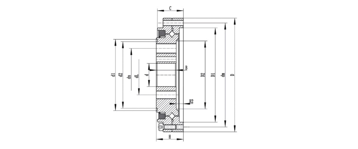
| Bearing type | Overall Dimension(mm) | Installation Hole Size(PCD&SPEC) | Weight | |||||||||
| D | d | C | H | B | dm | dn | dl | kg | ||||
| CSF(G)-14 | 55 | 11 | 16 | 16.5 | 13.5 | 49 | 8-φ3.5 | 23 | 6-M4 | 17 | 6-M4 | 0.15 |
| CSF(G)-17 | 62 | 10 | 16 | 16.5 | 13.5 | 56 | 10-φ3.5 | 27 | 6-M5 | 19 | 6-M5 | 0.24 |
| CSF(G)-20 | 70 | 14 | 16 | 16.5 | 13.5 | 64 | 12-φ3.5 | 32 | 8-M6 | 24 | 8-M5 | 0.3 |
| CSF(G)-25 | 85 | 20 | 18 | 18.5 | 16.5 | 79 | 16-φ3.5 | 42 | 8-M8 | 30 | 8-M6 | 0.45 |
| CSF(G)-32 | 112 | 26 | 21.5 | 22.5 | 19 | 104 | 16-φ4.5 | 55 | 8-M10 | 40 | 8-M8 | 0.9 |
| CSF(G)-40 | 126 | 24/32 | 22.5 | 24 | 21.5 | 117 | 20-φ5 | 68 | 8-M10 | 50 | 8-M10 | 1.3 |
| CSF(G)-50 | 157 | 32/40 | 30 | 31 | 28 | 147 | 16-φ5.5 | 84 | 8-M14 | 60 | 8-M14 | 2.8 |
| CSF(G)-65 | 210 | 44/52 | 37 | 39 | 35 | 198 | 20-φ6.5 | 110 | 8-M16 | 80 | 8-M16 | 7.9 |

0+
years
Industry Experience

0+
Model diversity

0+
Number of Employees

0
$
Annual export value

Understanding Crossed Tapered Roller Bearings in Modern Engineering Crossed tapered roller bearings represent a significant advancement in mechanical engineering, offering unprecedented precision and...
Introduction: The Engineering Backbone of Articulated Systems In mechanical design, few components are as deceptively simple yet critically important as the rod end bearing. The SIZJ12 bearing repres...
The selection of a four-row tapered roller bearing for rolling mill roll neck applications is rarely a straightforward choice. Engineers and maintenance professionals must evaluate multiple variables...
SI5 Bearing: Specifications & Selection Essentials For any application requiring a compact, steel-on-steel rod end bearing with a 5 mm bore and M5 thread, the SI5 series — specifically the SI5E ...
Product Categories
Contact Us

Jane@ukl-bearing.com
Jenny@ukl-bearing.com
Andy@ukl-bearing.com
Ivy@ukl-bearing.com

+86-510- 88763239
+86-15371057968

No.1 Hehuan Road, Hudai Town, Binhu District, Wuxi City.
Ready to Begin?
Get in Touch

Now!
UKL BEARING
 English
 Español
 русский


 Series Integrated High Rigidity Harmonic Drive Bearing")


