Content
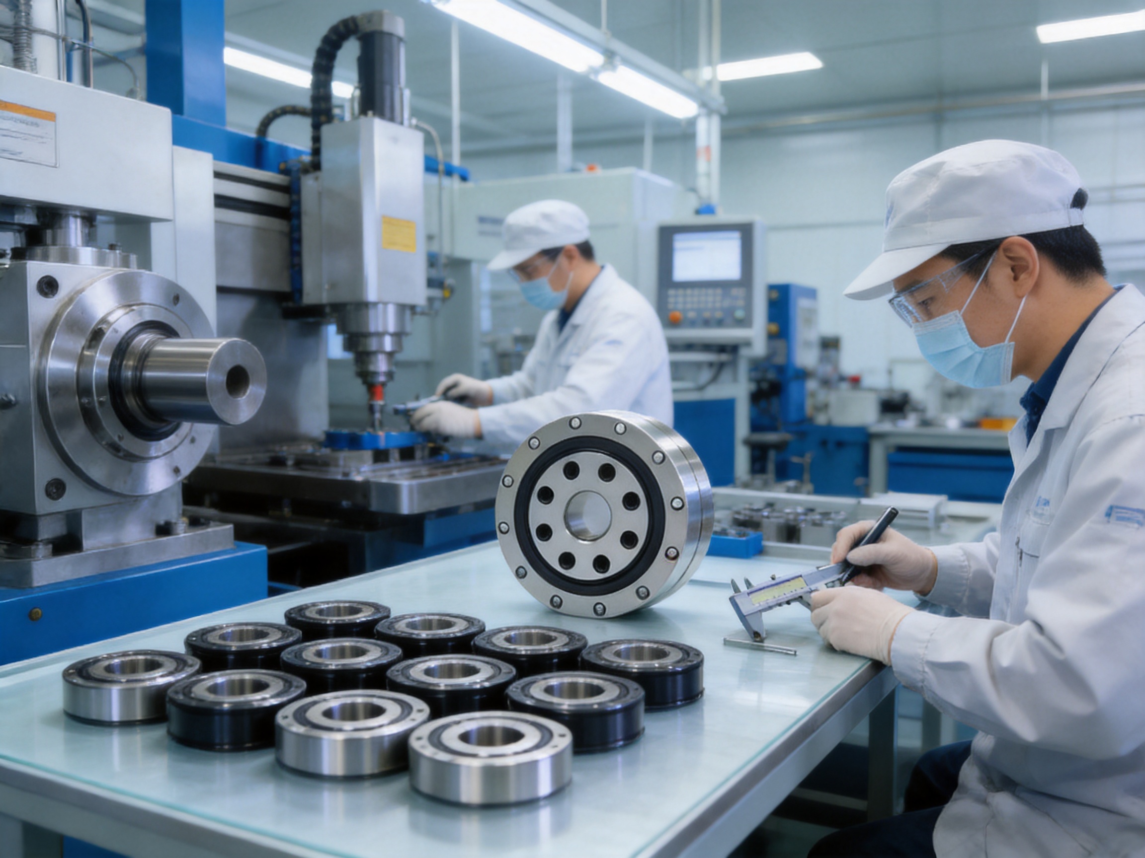
Modern robots and automated machines require bearing systems that deliver more than simple rotational support. Their bearings must withstand combined loads, preserve positional accuracy, occupy minimal installation space, and operate reliably through repeated acceleration, deceleration, and reversing motion. In harmonic reducer assemblies, these requirements become especially demanding because the bearing is directly involved in transmitting motion between compact, highly precise components.
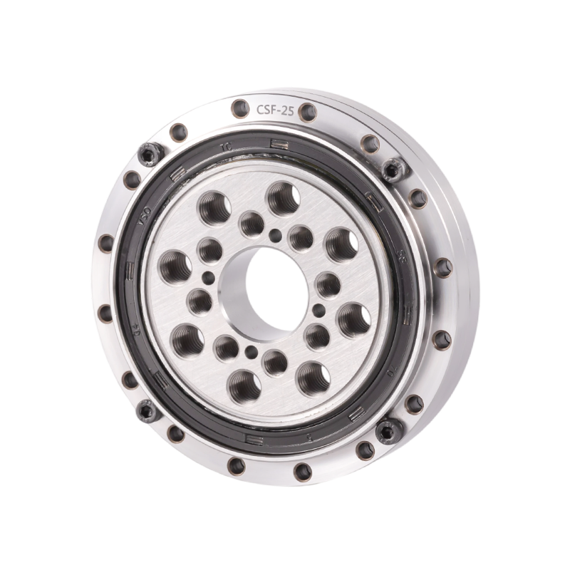
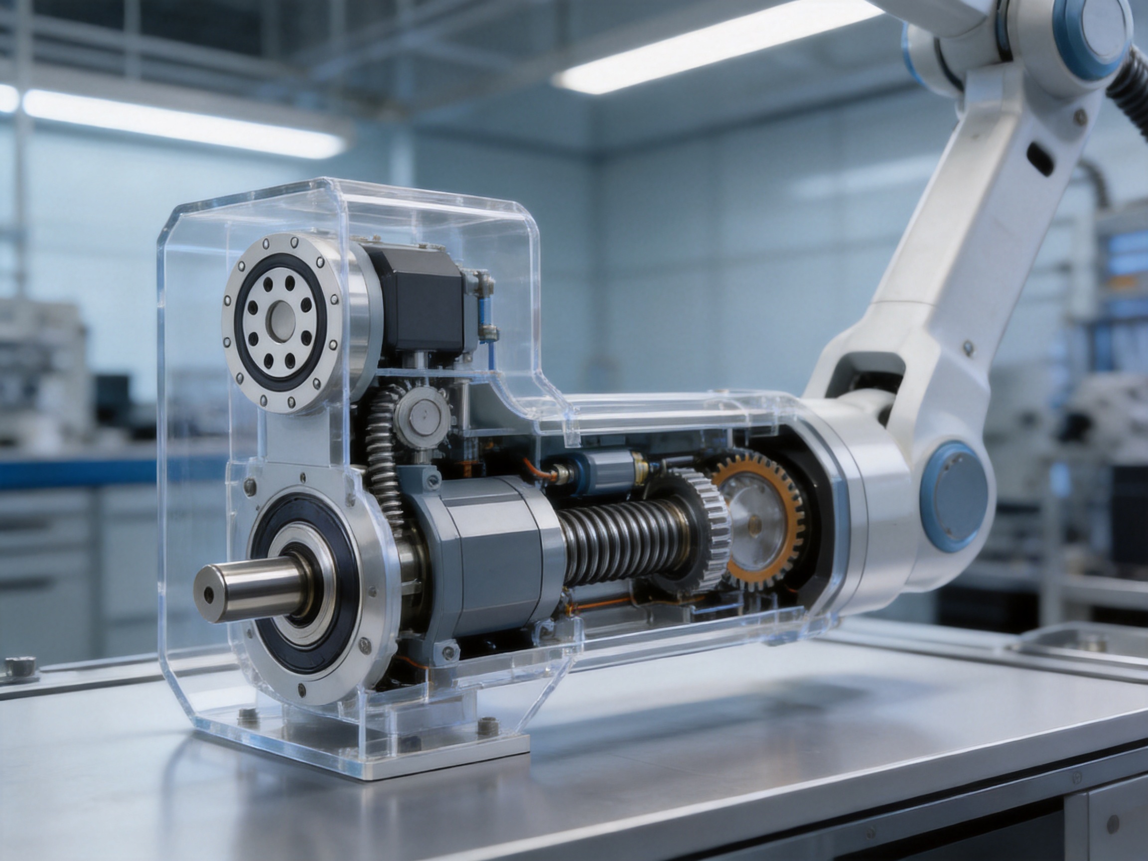
The CSD harmonic reducer bearing is designed for this demanding environment. It is primarily used in the output section of CSD series harmonic reducers, where rigidity, compactness, load capacity, and precision have a direct effect on the performance of the complete reducer. Its outer ring and inner ring each use an integrated one-piece structure. Compared with separated or assembled ring designs, this configuration provides a strong and stable load-bearing foundation while maintaining a compact envelope.
The CSD type has an outer diameter comparable to the CSG type, but its integrated construction gives it higher structural strength than CSG type components. This makes the CSD bearing particularly suitable for robotic joints, precision automation equipment, aerospace mechanisms, medical devices, and other motion-control systems in which limited installation space must be combined with demanding mechanical performance.
A harmonic reducer is a compact precision transmission mechanism generally composed of a wave generator, a flexible spline, and a circular spline. Its operating principle allows a large reduction ratio to be achieved in a relatively small package. The mechanism is valued for its high positioning accuracy, low backlash, coaxial arrangement, and ability to transmit motion in robotic joints and other compact drive systems.
Although the gear elements receive much of the attention, the output bearing is equally important. The bearing supports the output structure, manages radial and axial forces, maintains alignment, and permits smooth rotation between the moving and stationary parts. If the bearing lacks stiffness or dimensional stability, the advantages of the harmonic reducer can be reduced by unwanted deflection, vibration, friction, or positioning error.
In a robotic arm, for example, the output bearing may be exposed to the weight of the arm, payload-related overturning moments, repeated start-and-stop cycles, and external forces caused by contact with a workpiece. These loads are not always purely radial. Depending on the joint design, the bearing may also experience axial loading and moment loading. Consequently, the bearing must support the complete output assembly while preserving the geometric relationship between the reducer and the robot link.
The CSD bearing is developed around these operating conditions. Its one-piece ring construction supports a rigid connection between the mounting structure and the rolling elements. This helps the bearing function as a structural component rather than merely a replaceable rolling element assembly.
The most important design characteristic of the CSD type is the integrated structure of both the outer ring and the inner ring. Each ring is manufactured as a single body instead of being formed from multiple separate sections assembled during installation. This arrangement reduces the number of structural interfaces in the load path.
A reduced number of interfaces can provide several practical benefits. First, the load is distributed through a continuous ring body. Second, the mounting surfaces can be produced with a consistent relationship to the bearing raceway. Third, the assembled reducer can achieve a more stable connection between the bearing, housing, and output flange. These factors are important in high-precision systems where small changes in mounting condition can influence runout, stiffness, noise, and service life.
The integrated structure also simplifies the mechanical architecture of the reducer. In a compact design, every additional flange, joint, or separate ring can consume axial space or require extra fasteners. The CSD type is intended to provide the necessary bearing function without imposing an unnecessarily large structural package.
Another advantage is improved resistance to deformation. When a bearing ring is divided into several components, the connection between those components may become a local source of movement under high load. A one-piece ring reduces this risk and helps maintain the intended geometry of the bearing. This is particularly useful in robotic joints that repeatedly reverse direction and experience fluctuating moment loads.
The CSD type is designed for use in the output section of CSD series harmonic reducers. Its dimensions and mounting-hole arrangements are configured to support direct integration with the corresponding reducer architecture. Correct matching of bearing size, reducer housing, output flange, fasteners, and installation tolerances remains essential for achieving the designed performance.
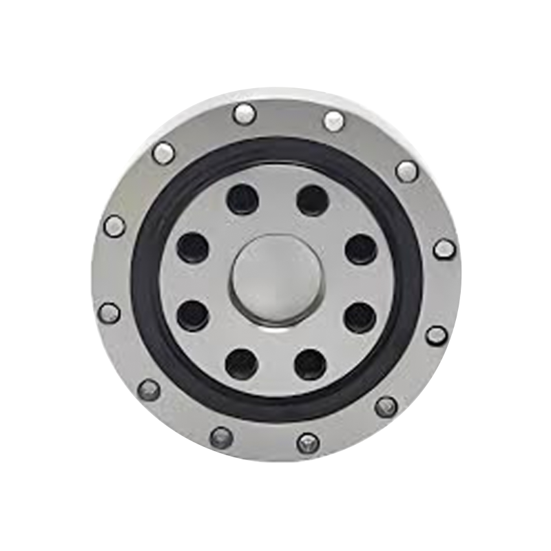
CSD Robot Harmonic Reducers Bearing
Space is a major design constraint in industrial robots. A smaller joint can reduce the overall mass of a robotic arm, improve acceleration performance, and make it easier to reach confined work areas. Compactness can also lower the amount of material used in the housing and reduce the size of connected motors, cables, and protective covers.
The CSD bearing uses a compact load-bearing structure that maintains useful load capacity without requiring an oversized external package. Its outer diameter is the same as that of the CSG type, allowing designers to work within a familiar installation envelope while benefiting from the stronger CSD construction. This is valuable when a robot platform is being upgraded and the available housing diameter is already fixed.
Compared with a bearing arrangement that relies on multiple separate bearing components, the integrated CSD structure can help reduce the number of surrounding parts. Fewer parts may simplify the housing design, reduce assembly operations, and create more freedom for motor and cable routing.
The CSD design is intended to offer higher strength than CSG type components while maintaining a similar outer diameter. Structural strength is important because harmonic reducer bearings often carry not only rotational loads but also the moment generated by the distance between the payload and the joint axis.
Higher strength helps the bearing resist elastic deformation during acceleration, deceleration, and external loading. Lower deformation can contribute to improved repeatability and a more stable relationship between commanded movement and actual output movement. It can also help reduce the likelihood that excessive deflection will create uneven contact stress or abnormal wear.
This advantage is especially relevant in applications where a robot must handle changing payloads. A joint that carries a light gripper during one operation may support a heavier tool or workpiece during another. The bearing must accommodate these changes without compromising the accuracy of the complete reducer assembly.
Backlash is the relative movement that can occur when the direction of rotation changes because of clearance within a transmission system. Harmonic reducers are selected partly because they can provide very low backlash. However, the bearing arrangement also affects overall motion behavior. Bearing clearance, mounting deformation, ring movement, and output-flange deflection can all influence the practical accuracy of the joint.
The CSD bearing is manufactured for precision harmonic drive applications. Its integrated rings and accurate mounting interfaces help maintain the alignment needed for controlled output movement. By supporting the reducer structure firmly, the bearing helps the complete assembly preserve its designed low-backlash characteristics.
It is important to understand that bearing design alone does not determine the total backlash of a robot joint. Gear geometry, preload, machining accuracy, lubrication, assembly, control software, and load conditions also contribute. Nevertheless, a stable and accurately manufactured output bearing is a necessary foundation for achieving the performance expected from a precision harmonic reducer.
The output bearing must distribute forces through the rings and rolling elements while maintaining smooth rotation. A rigid, continuous ring structure helps provide a consistent raceway foundation. This can improve the distribution of contact forces and reduce localized stress caused by ring distortion or mounting inconsistency.
Better load distribution is beneficial in applications involving frequent motion reversals. Reversing motion can change the direction of contact forces and produce repeated stress cycles. The CSD configuration is intended to provide a stable structural response under these conditions, supporting longer and more predictable operating performance when the bearing is correctly selected, lubricated, mounted, and loaded within its specifications.
Robotic and automated equipment often depends on repeatable movement rather than simply high rotational speed. A bearing with accurate dimensions, controlled runout, and consistent internal geometry helps the reducer maintain smooth, repeatable movement.
The CSD product is produced through precision manufacturing processes designed for strict accuracy and performance requirements. The objective is not only to achieve a nominal dimension but also to control the relationships among the raceways, mounting faces, bolt circles, and bearing axis. This dimensional consistency supports easier integration and more predictable results during assembly.
The CSD series is available in several sizes, allowing designers to select a bearing according to reducer size, shaft arrangement, load requirement, and available space. The listed models include CSD-14, CSD-17, CSD-20, CSD-25, CSD-32, CSD-40, and CSD-50.
The model number should not be selected only by comparing the outside diameter. Engineers should also review the mounting-hole pattern, inner and outer mounting dimensions, basic dynamic load rating, basic static load rating, weight, and the expected radial, axial, and moment loads. The reducer manufacturer’s interface requirements must be checked at the same time.
| Model | D1 | D2 | D | H | C | B | H2 | CR (kN) | COR (kN) | Weight (kg) |
|---|---|---|---|---|---|---|---|---|---|---|
| CSD-14 | 12 | 11 | 55 | 16.6 | 16.1 | 13.9 | 2.7 | 4.7 | 6.7 | 0.24 |
| CSD-17 | 14 | 11 | 62 | 16.6 | 16.1 | 13.9 | 2.7 | 5.3 | 7.5 | 0.30 |
| CSD-20 | 18 | 16 | 70 | 18.3 | 17.8 | 15.6 | 2.7 | 5.8 | 9.0 | 0.42 |
| CSD-25 | 24 | 20 | 85 | 23.4 | 22.9 | 20.0 | 3.4 | 9.6 | 15.1 | 0.80 |
| CSD-32 | 32 | 30 | 112 | 24.5 | 23.5 | 20.9 | 3.6 | 15.0 | 25.0 | 1.40 |
| CSD-40 | 36 | 32 | 126 | 29.1 | 28.1 | 24.6 | 4.5 | 21.3 | 36.5 | 2.10 |
| CSD-50 | 48 | 44 | 157 | 34.0 | 33.0 | 29.4 | 4.6 | 34.8 | 60.2 | 3.80 |
The values in the table are provided in millimeters for dimensional data, kilonewtons for load ratings, and kilograms for weight. D, H, C, B, and H2 correspond to the dimensional categories supplied for the product. Because mounting-hole specifications contain detailed patterns and thread depths, the complete drawing should be reviewed before production or installation.
The model range provides a progression from small, lightweight units to larger bearings with higher basic load ratings. The CSD-14 and CSD-17 are suitable for compact robotic joints and light automation mechanisms when their calculated loads are within limits. The CSD-32, CSD-40, and CSD-50 provide greater load capacity for larger joints, higher payloads, or more demanding moment conditions.
The CSD bearing includes dedicated outer-ring and inner-ring mounting-hole arrangements. These patterns are an important part of the product’s integration advantage because the bearing can be secured directly to the surrounding reducer and output components. The mounting interface must be designed with correct bolt diameter, thread depth, pitch-circle diameter, hole count, and tightening sequence.
For example, the CSD-14 has an outer-ring pattern including six 3.5-millimeter holes, while its inner-ring arrangements include M2 and M3 threaded holes with specified depths. Larger models use larger thread sizes and different numbers of mounting holes. These details are not interchangeable between models. A housing intended for one model should not be assumed to accept another model solely because the outside dimensions appear similar.
Mounting surfaces should be clean, flat, and free from burrs. Uneven surfaces can distort the bearing ring after the fasteners are tightened. Such distortion may increase rotational torque, reduce accuracy, and create uneven raceway loading. For precision reducer assemblies, housing and flange tolerances should be verified with suitable inspection equipment before final assembly.
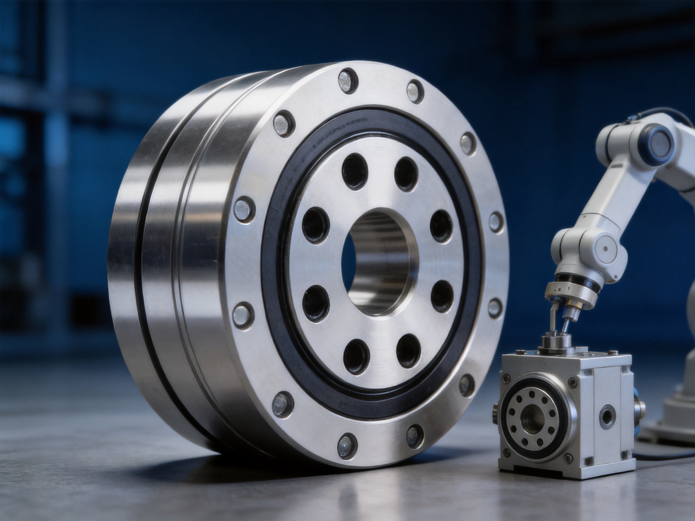
The performance of a precision bearing depends on the complete manufacturing chain. Material quality, forging or forming, turning, heat treatment, grinding, assembly, cleaning, lubrication, sealing, inspection, and packaging all influence the final result. A bearing with an excellent design cannot deliver consistent performance if the production process is not controlled at every stage.
UKL Bearing Manufacturing Co., Ltd. integrates research and development, production, and international distribution. Its manufacturing operations cover forging, turning, heat treatment, grinding, assembly, and packaging. This integrated process enables the company to coordinate manufacturing stages and maintain control over critical product characteristics.
The bearing ring begins with suitable bearing-grade steel and a controlled forming process. Forging or other controlled forming operations can help establish a strong material structure before machining. Proper material preparation is essential because the rings must withstand repeated rolling contact, fluctuating loads, and long-term stress cycles.
At this stage, process control should address material traceability, heating conditions, forming accuracy, and the removal of defects. Consistent material handling creates a reliable foundation for subsequent heat treatment and grinding operations.
Turning establishes the primary geometry of the inner and outer rings. The machining operation forms the basic dimensions, mounting surfaces, shoulders, and other features required for later grinding and assembly. For integrated-ring bearings, the accuracy of these features is particularly important because the ring itself also serves as a structural mounting component.
Controlled turning reduces the amount of material that must be removed during final grinding. It also helps ensure that the bearing’s mounting dimensions remain within a stable process range. Digital production control and in-process inspection can identify deviations before they affect later operations.
Heat treatment gives the bearing rings the hardness and internal structure needed to resist rolling-contact fatigue and wear. The process must be controlled carefully because excessive distortion can affect the raceway, mounting faces, and ring geometry.
After heat treatment, rings are normally inspected for hardness, dimensional stability, and visible defects. The relationship between heat-treatment conditions and final grinding allowance must be managed so that the finished component can achieve the required accuracy without excessive material removal.
Grinding is one of the most important operations for a precision bearing. The raceway profile, surface finish, roundness, and dimensional accuracy influence rolling smoothness, friction, noise, load distribution, and service life. The mounting faces and diameters must also be ground or finished to maintain the required relationship with the bearing axis.
For harmonic reducer applications, grinding quality supports the low-friction, low-vibration movement expected from a precision motion-control system. A consistent raceway allows the rolling elements to move smoothly and helps reduce local stress concentrations.
During assembly, the rings, rolling elements, cage, seals, and lubricant must be combined under controlled conditions. Cleanliness is essential because small particles can create noise, increase wear, and damage precision raceways. Assembly personnel and equipment must prevent contamination and protect finished surfaces from impact.
Final inspection may include dimensional checks, rotational torque testing, runout measurement, visual examination, noise and vibration evaluation, and verification of the mounting-hole geometry. The precise inspection program depends on the bearing configuration and customer requirements. For OEM applications, inspection data and traceability records can support process validation and incoming-quality control.
UKL reports a monthly production capacity of approximately 10,000 to 50,000 units and operates multiple production lines. This combination of manufacturing capacity and process integration supports both regular production and customized OEM or ODM requirements. Capacity alone does not guarantee quality, but a structured production system can help maintain delivery continuity when supported by appropriate inspection and process-management procedures.
The company’s research and development activities include high-precision cross roller bearings, dual-direction thrust angular contact ball bearings, and other products for CNC machines, robotics, and intelligent automation systems. This product knowledge is relevant to the CSD bearing because harmonic reducers are part of a broader precision-motion ecosystem.
Experience with different bearing architectures helps engineers evaluate load paths, stiffness, sealing, lubrication, mounting, and application conditions. It also supports communication with customers who may require modifications to dimensions, materials, preload, accuracy class, sealing, or packaging.
Industrial robots use reducer bearings in articulated joints, rotary positioning axes, welding systems, assembly arms, material-handling equipment, and inspection platforms. The CSD bearing is suitable for applications that require compact dimensions, accurate positioning, and support for combined loading.
In a robot joint, the bearing supports the output flange and transfers the load from the link to the reducer housing. Its stiffness affects the joint’s resistance to deflection, while its accuracy affects repeatability. The bearing must also tolerate many cycles over its service life, often under varying speed and load conditions.
Collaborative robots and compact robot arms are designed to work near people or within restricted spaces. Their joints must be lightweight and compact while still providing controlled movement. A smaller bearing envelope can help reduce joint size and simplify the design of protective covers and safety mechanisms.
Because collaborative systems may change speed and direction frequently, smooth rotation and predictable friction are important. Correct preload, lubrication, sealing, and mounting are necessary to obtain the intended result from the CSD bearing.
Aerospace equipment places strict demands on mass, reliability, vibration resistance, and environmental performance. The compact structure of the CSD bearing may be beneficial where available space and system weight are limited. However, aerospace applications require additional verification of materials, lubrication, temperature range, cleanliness, and qualification procedures.
The bearing should be evaluated against the complete environmental profile, including temperature variation, vacuum or low-pressure conditions, vibration, shock, and long periods of storage or inactivity. Product selection should be confirmed through an application-specific engineering review.
Medical automation systems, imaging equipment, surgical positioning mechanisms, and laboratory robots require precise, smooth, and repeatable movement. The CSD bearing can support compact positioning systems where the output assembly must remain stable while moving accurately.
Medical equipment designers may also require special requirements related to cleanliness, noise, lubricant compatibility, sterilization, and documentation. These factors should be discussed before production so that the bearing configuration matches the equipment’s regulatory and operating conditions.
Precision machine tools and automated production lines depend on stable motion under repetitive duty cycles. Bearings in rotary tables, indexing mechanisms, tool-changing systems, and robotic loading devices must maintain accuracy while exposed to vibration, cutting forces, or rapid movement.
The CSD type is particularly relevant when a harmonic reducer is used to create a compact high-ratio drive. Its integrated structure can help the machine designer create a rigid and space-efficient assembly.
Before selecting a model, calculate the radial load, axial load, overturning moment, operating speed, acceleration, duty cycle, and expected service life. Payload mass alone is not sufficient. The distance from the joint axis to the payload center of gravity can create a significant moment that must be considered in the bearing selection.
Dynamic load rating is associated with fatigue life under moving conditions, while static load rating is used to evaluate permanent deformation risk under stationary or slowly moving loads. Both values should be considered, along with the actual combined-load calculation recommended by the application engineer.
The mating surfaces should be clean, flat, and free of burrs. The housing and output flange should have suitable dimensional tolerances and sufficient rigidity. If the surrounding components deform under bolt load, the bearing ring may also deform and cause increased torque or reduced accuracy.
Mounting holes must match the model drawing. Thread depth should be respected so that fasteners do not bottom out or interfere with internal components. Bolts should be tightened in a controlled, progressive sequence using the specified torque and suitable equipment.
Precision bearings should remain in their protective packaging until installation. They should not be placed directly on dirty benches or dragged across metal surfaces. Impacts, excessive pressing force, and incorrect tools can damage raceways, mounting faces, or seals.
When pressing or positioning the bearing, force should be applied to the ring that is receiving the interference or installation load. Force transmitted through the rolling elements can create indentations and cause premature failure.
Lubrication reduces friction, controls heat, protects raceways, and helps prevent wear. The lubricant type, quantity, viscosity, and replenishment interval should match the bearing speed, temperature, load, sealing arrangement, and reducer environment. Incompatible greases should not be mixed.
Too little lubricant may result in insufficient film thickness and increased wear. Too much lubricant can generate heat, increase churning losses, and raise operating torque. The recommended lubrication procedure should be confirmed for the specific reducer assembly.
Dust, metal particles, moisture, and cleaning-fluid residue can reduce bearing life. The assembly area should be clean, and components should be inspected before installation. If the bearing is sealed, the seals should not be removed unnecessarily. If the reducer uses an external sealing system, the sealing arrangement should be checked for correct compression and alignment.
After installation, rotate the assembly by hand or at low speed to confirm smooth movement. Check for abnormal noise, excessive torque, interference, or uneven resistance. Initial testing should be performed without full payload whenever possible. Operating temperature, vibration, and positioning behavior should be monitored during commissioning.
Service life depends on load, speed, lubrication, contamination, mounting accuracy, operating temperature, vibration, shock, and maintenance quality. The CSD bearing is designed for demanding precision applications, but no bearing can compensate for excessive loading or improper installation.
Routine maintenance should include inspection of reducer housing fasteners, seal condition, lubricant condition, operating temperature, rotational smoothness, and abnormal noise. In robotic systems, cable interference and collision events should also be checked because an external impact can damage the bearing or distort the mounting structure even when the robot continues to operate.
Monitoring trends is often more useful than relying on a single measurement. A gradual increase in torque, vibration, temperature, or positioning error may indicate lubrication deterioration, contamination, mounting loosening, raceway damage, or an external alignment problem.
When replacing a bearing, the surrounding components should also be inspected. A worn housing, damaged flange, or distorted mounting surface may cause a new bearing to fail prematurely. Replacement parts should be matched by model and specification rather than by approximate dimensions.
For OEMs and distributors, the value of a bearing supplier extends beyond the individual component. Consistent quality, stable production, responsive engineering, reliable packaging, and technical communication are all important to the final equipment manufacturer.
UKL Bearing Manufacturing Co., Ltd. combines manufacturing and trading functions and serves customers across Europe, Asia, Africa, Russia, and other markets. The company states that it has more than 15 years of OEM and ODM export experience and a workforce of approximately 201 to 500 employees. Its international service structure is intended to support technical communication, order coordination, installation guidance, and after-sales maintenance.
An integrated supplier can coordinate design feedback with production capabilities. If an application requires a modified mounting pattern, different sealing arrangement, special packaging, or a customized bearing specification, the supplier can review the request through its engineering and manufacturing teams. This can reduce communication gaps between a trading office, an external factory, and the end customer.
Production covering forging, turning, heat treatment, grinding, assembly, and packaging also supports better control of lead times and process consistency. For high-volume robot or automation programs, this coordination can be important because changes to one manufacturing stage may affect the dimensional results of later stages.
The company also emphasizes environmentally responsible manufacturing, material recycling, and energy optimization. These efforts support customers that are developing more sustainable supply chains. Environmental claims should be evaluated through the specific certifications and documentation required by the customer, but sustainability awareness is increasingly relevant in industrial procurement.
The CSD bearing should be compared with alternative bearing arrangements according to the actual machine requirements. A conventional combination of radial bearings may be suitable for some systems, but it can require more axial space, additional spacers, and more complex preload adjustment. A cross roller bearing may provide excellent rigidity and moment capacity in certain applications, but its geometry, cost, and installation requirements may differ from those of an integrated harmonic reducer bearing.
Separated ring designs can offer flexibility during assembly, but they may introduce additional interfaces and require careful control of the relationship between individual components. The CSD one-piece ring design is intended to simplify the structural load path and provide a strong connection between the reducer and the output assembly.
Compared with a smaller bearing selected only for envelope size, the CSD design offers a stronger solution for applications where moment loading and structural stiffness are important. Conversely, the largest available model should not automatically be selected. Oversizing can increase mass, cost, inertia, and drive requirements. Proper engineering calculation remains the best method for choosing the appropriate model.
The principal competitive advantages of the CSD type can therefore be summarized as compact integration, higher strength than the CSG type at a comparable outer diameter, precision manufacturing, dedicated mounting-hole arrangements, and suitability for high-accuracy harmonic reducer applications.
Robot manufacturers often require more than a standard catalog item. They may need a specific mounting interface, customized lubrication, special sealing, a controlled internal clearance, a particular accuracy grade, or packaging suitable for automated assembly. These requirements should be stated clearly at the quotation and design-review stage.
Useful technical information includes the reducer model, operating speed, acceleration profile, load spectrum, payload, moment arm, expected service life, operating temperature, environment, available space, and assembly method. Drawings of the housing and output flange can help the supplier confirm compatibility.
Customization should not be limited to changing a hole pattern. Any modification to the ring geometry, raceway, rolling elements, preload, material, heat treatment, or sealing can affect load capacity and operating behavior. A responsible engineering process should review the complete design and validate prototypes before mass production.
UKL’s experience with OEM and ODM projects provides a basis for discussing such requirements. The company’s research and development capabilities in robotics, CNC equipment, and intelligent automation are relevant to customers developing new motion-control assemblies.
The CSD bearing is primarily used in the output section of CSD series harmonic reducers. It supports the output structure, maintains alignment, carries combined loads, and enables precise rotational movement in robotics and automation equipment.
Both the outer ring and inner ring of the CSD type use an integrated one-piece structure. Its outer diameter is the same as that of the CSG type, while the CSD structure provides higher strength than CSG type components.
No. The bearing supports the reducer structure and helps preserve accurate alignment, but total system backlash also depends on gear geometry, reducer assembly, preload, machining accuracy, lubrication, load, and control conditions. The CSD bearing is designed to support low-backlash harmonic drive performance rather than independently eliminate every source of backlash.
Typical applications include industrial robotics, compact robotic joints, aerospace mechanisms, medical equipment, CNC machines, automated production systems, and other high-precision motion-control equipment.
Selection should consider radial load, axial load, overturning moment, speed, acceleration, duty cycle, service life, mounting space, hole pattern, and environmental conditions. The model’s basic dynamic and static load ratings should be compared with the calculated application loads.
No. Each model has its own outer-ring and inner-ring hole counts, diameters, thread sizes, thread depths, and pitch-circle dimensions. The complete dimensional drawing should be checked before designing the housing or output flange.
Yes, it can be considered for new harmonic reducer and robotic joint designs, provided the mechanical interface, load conditions, lubrication, sealing, and accuracy requirements are reviewed with the supplier. Prototype testing is recommended before mass production.
The manufacturing chain includes forging, turning, heat treatment, grinding, assembly, and packaging. These processes are coordinated with inspection and production controls to establish accurate raceways, mounting surfaces, ring dimensions, and assembly quality.
Check the housing flatness, mounting-hole dimensions, bolt specifications, cleanliness, alignment, lubrication, tightening sequence, and rotational torque. Avoid applying installation force through the rolling elements and verify smooth operation after assembly.
The company provides OEM and ODM export services and can discuss customized requirements such as mounting interfaces, sealing, lubrication, packaging, and application-specific specifications. Engineering review is needed to confirm feasibility and performance.
The CSD harmonic reducer bearing is designed for the demanding output sections of compact, high-precision harmonic drive systems. Its integrated outer and inner rings create a strong, continuous structural foundation while maintaining an outer diameter comparable to the CSG type. This combination gives designers an opportunity to achieve higher strength without substantially increasing the installation envelope.
Its value is most apparent in robotic joints and automated mechanisms that must combine compactness, low-backlash motion, rigidity, repeatability, and long-term reliability. The available range from CSD-14 to CSD-50 supports different equipment sizes and load requirements, while dedicated mounting-hole arrangements simplify integration with compatible reducer structures.
The product’s performance is supported by an integrated manufacturing system that includes material preparation, forming, turning, heat treatment, grinding, assembly, inspection, and packaging. UKL Bearing Manufacturing Co., Ltd. combines these production capabilities with research and development experience in precision bearings, robotics, CNC machines, and intelligent automation. This makes the company suitable for customers seeking both standard products and application-specific engineering support.
For the best results, the CSD bearing should be selected as part of a complete mechanical system. Load calculations, mounting accuracy, lubrication, sealing, contamination control, assembly procedures, and commissioning tests all influence the final performance. When these factors are properly managed, the CSD integrated harmonic reducer bearing can provide a compact and dependable foundation for advanced robotic and motion-control equipment.
1. Product technical information for CSD harmonic reducer bearings, including model dimensions, mounting-hole arrangements, load ratings, and weights.
2. General principles of rolling-bearing load ratings, fatigue life, static capacity, lubrication, and installation practice.
3. Technical literature on harmonic drive reducers, wave generators, flexible splines, circular splines, backlash, and robotic joint design.
4. Engineering guidelines for precision bearing mounting, housing tolerances, flange rigidity, bolt tightening, cleanliness, and condition monitoring.
5. Manufacturing process references covering bearing-steel preparation, forging, turning, heat treatment, grinding, assembly, inspection, and packaging.
6. Industrial robotics and automated motion-control application practices for radial, axial, and moment-loaded reducer bearings.
7. UKL Bearing Manufacturing Co., Ltd. company and manufacturing information supplied for this product article.
Product Categories
Contact Us

Jane@ukl-bearing.com
Jenny@ukl-bearing.com
Andy@ukl-bearing.com
Ivy@ukl-bearing.com

+86-510- 88763239
+86-15371057968

No.1 Hehuan Road, Hudai Town, Binhu District, Wuxi City.
Ready to Begin?
Get in Touch

Now!
UKL BEARING
 English
 Español
 русский