Content
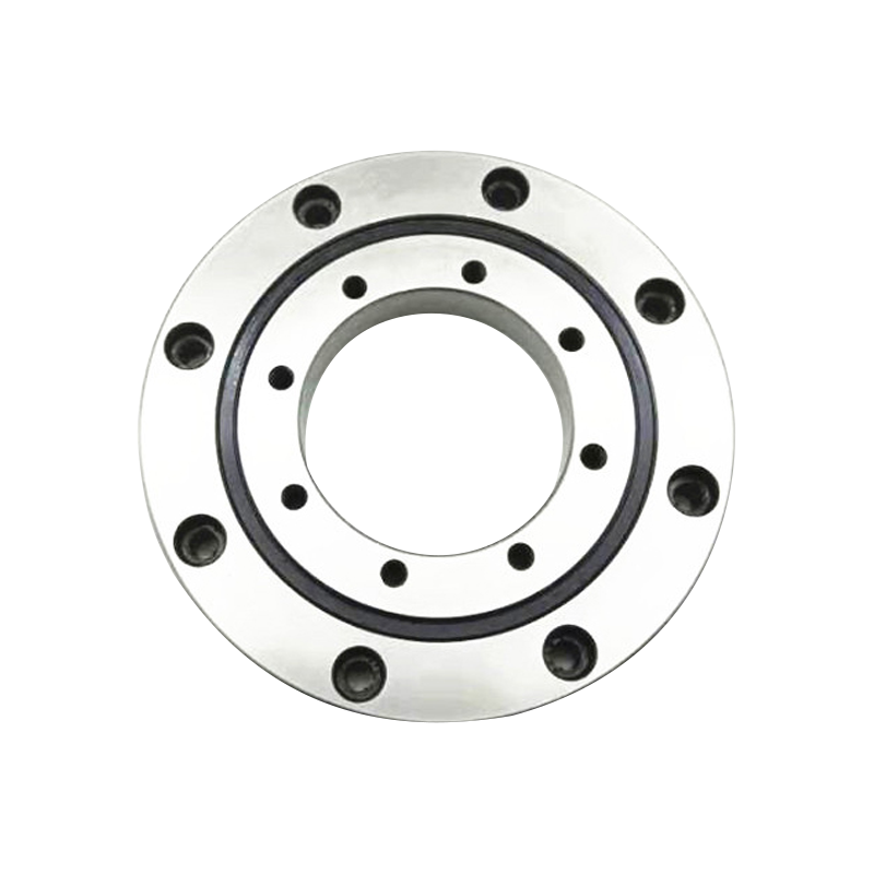
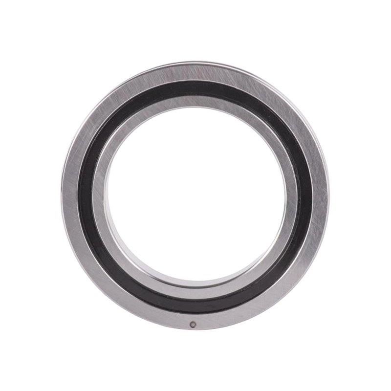
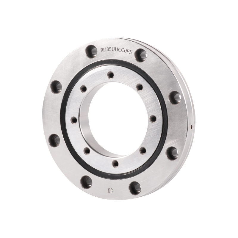
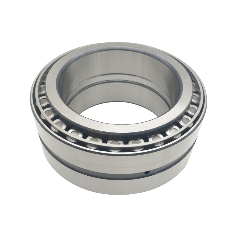
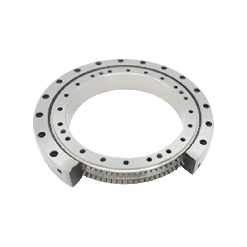
Crossed tapered roller bearings represent a significant advancement in mechanical engineering, offering unprecedented precision and load-carrying capabilities for demanding industrial applications. These sophisticated components combine the advantages of both crossed roller bearings and tapered designs, creating a solution that addresses the complex requirements of modern machinery.
The fundamental appeal of tapered roller bearings lies in their ability to support combined radial and axial loads simultaneously, while maintaining exceptional rotational accuracy. When these principles are integrated with a crossed configuration, the result is a bearing system capable of handling extreme load conditions while preserving the tight tolerances essential for precision rotary applications.
Industries ranging from semiconductor manufacturing to aerospace component assembly increasingly rely on these bearings to ensure product quality and equipment reliability. The precision specifications of crossed tapered roller bearings make them indispensable for applications where even microscopic misalignment can compromise operational efficiency or product quality.
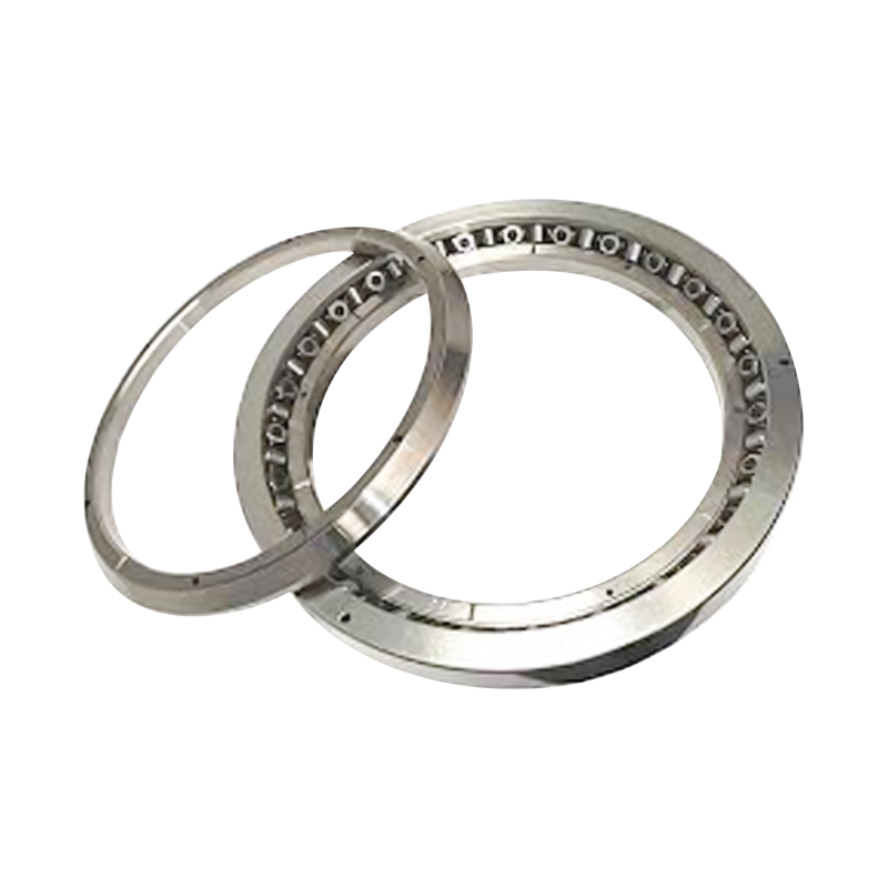
A crossed tapered roller bearing consists of four primary elements working in coordinated harmony: the outer raceway, inner raceway, tapered rollers, and cage assembly. Each component is engineered with meticulous precision to ensure optimal load distribution and minimal friction.
The outer raceway features a precisely angled surface that matches the taper angle of the rollers, typically ranging from 10 to 25 degrees depending on application requirements. This geometry enables the bearing to accept loads approaching the axis of rotation, which distinguishes it from traditional cylindrical roller designs.
Inner raceway geometry mirrors the outer race configuration but is often incorporated into a unified housing structure. This design reduces the number of separate components requiring alignment, thereby simplifying installation while improving system reliability.
The tapered rollers themselves represent a critical innovation in bearing design. Unlike cylindrical rollers that distribute load uniformly across their length, tapered rollers concentrate load in a controlled manner that maximizes contact stress efficiency.
The taper angle of individual rollers typically ranges from 10 to 25 degrees, carefully selected based on the specific loading profile expected during operation. A shallower taper angle provides better radial load capacity, while steeper angles enhance axial load handling capability.
| Taper Angle | Radial Load Capacity | Axial Load Capacity | Typical Application |
|---|---|---|---|
| 10 degrees | Very High | Moderate | Vertical spindle support |
| 15 degrees | High | High | Balanced load support |
| 20 degrees | Moderate | Very High | Thrust-dominant loading |
In a crossed tapered configuration, multiple bearing rings are arranged so that the tapered roller axes cross at a common point. This geometric arrangement delivers several critical advantages over traditional stacked bearing designs.
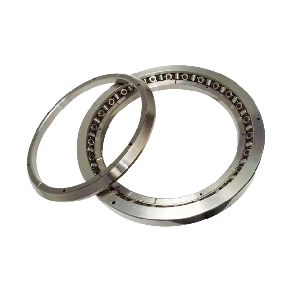
The XRT060-NT bearing represents a widely adopted standard in the crossed tapered bearing category, offering a balanced combination of size efficiency and load capacity. Understanding its dimensional parameters is essential for proper selection and integration into precision systems.
The dynamic load rating of 42,500 Newtons indicates the maximum bearing load that permits a theoretical operational life of 1 million revolutions. This metric proves particularly relevant when predicting bearing longevity under typical operating conditions.
The static load rating of 67,000 Newtons establishes the load threshold beyond which permanent deformation of bearing components becomes probable. This rating becomes critical during startup sequences, sudden load changes, or emergency braking events where dynamic conditions are not present.
The XRT060-NT bearing is available in multiple precision classifications, with P4 and P2 grades representing the most common industrial selections. P4 precision provides excellent performance for standard industrial applications, while P2 grade delivers the enhanced accuracy required for grinding operations, medical device manufacturing, and semiconductor processing equipment.
Precision grade selection directly influences rotational accuracy and permissible runout tolerances. P4 grade typically maintains radial runout within 0.005 millimeters, while P2 grade reduces this tolerance to approximately 0.002 millimeters.
In computer numerically controlled machine tool environments, crossed tapered roller bearing systems enable precision positioning stages to achieve the positional repeatability essential for high-quality manufacturing. CNC table applications subject bearings to complex multi-directional loads including vertical weight distribution, horizontal cutting forces, and rotational moments from spindle imbalance.
The crossed tapered configuration proves ideal for these applications because it accepts simultaneous radial and axial loads from a single compact unit. This capability eliminates the need for stacked bearing arrangements that would consume additional vertical space or compromise structural rigidity.
Industrial robot applications represent one of the most demanding bearing use cases in modern manufacturing. Robot slewing bearings must support the combined weight of end-effector assemblies, tool changers, and work pieces while maintaining precise angular positioning accuracy throughout millions of operational cycles.
A typical industrial robot slewing application might subject a bearing to radial loads exceeding 50,000 Newtons combined with axial loads reaching 30,000 Newtons, applied simultaneously during multi-axis motion. Crossed tapered designs handle these complex loading patterns more effectively than traditional alternatives, resulting in extended bearing life and improved positional repeatability.
Medical imaging systems such as computed tomography scanners and magnetic resonance imaging equipment employ precision bearings in their gantry rotation mechanisms. These applications demand exceptional rotational smoothness, minimal runout variation, and reliable performance across extended operating intervals without maintenance.
The stability characteristics of crossed tapered roller bearings prove essential for imaging quality, as any bearing deflection translates directly into image artifacts that compromise diagnostic accuracy. Hospitals and medical facilities depend on reliable bearing performance to minimize equipment downtime and maintain service schedules.
Wafer handling equipment, lithography machines, and precision metrology instruments rely on crossed tapered roller bearings for their exceptional moment load capacity and rotational accuracy. These applications often operate in controlled environment chambers where temperature stability is critical and traditional lubrication methods prove inadequate.
The precision grade specifications of crossed tapered bearings ensure that equipment can maintain sub-micron positioning accuracy throughout extended production runs, directly impacting manufacturing yield and product quality metrics.
The distinction between crossed tapered and crossed cylindrical roller bearing designs significantly influences bearing selection decisions. Both configurations offer crossed arrangement advantages, but their load distribution characteristics differ substantially.
| Performance Aspect | Crossed Tapered | Crossed Cylindrical |
|---|---|---|
| Axial Load Capacity | Excellent | Limited |
| Moment Load Handling | Superior | Good |
| Radial Load Capacity | High | Very High |
| Operating Temperature Range | -40 to 120C | -40 to 100C |
| Preload Adjustment Complexity | Moderate | Simple |
| Cost per Unit | Moderate | Lower |
Cylindrical roller designs concentrate load across the full roller length, creating a line contact that distributes forces uniformly. This geometry delivers maximum radial stiffness per unit size, making cylindrical configurations ideal for applications dominated by purely radial loading.
Tapered roller configurations establish point contact patterns that concentrate load at the roller ends, then distribute this load through the tapered geometry toward the bearing center. This arrangement sacrifices some radial load capacity to gain superior axial and moment load handling characteristics.
Engineers should select crossed tapered configurations when applications involve significant axial components, cantilevered loads, or complex multi-directional loading patterns. Crossed cylindrical designs prove more economical when radial load dominates and axial components remain minimal.
Preload represents a carefully controlled compressive force applied to bearing components prior to operational loading. This technique eliminates internal clearance and establishes a predictable load distribution that enhances stiffness, reduces noise, and improves rotational smoothness.
In crossed tapered roller bearing systems, preload adjustment directly influences several critical performance parameters including radial stiffness, axial runout, thermal stability, and noise generation. Achieving optimal preload requires balancing competing objectives: sufficient preload to ensure precision and rigidity, but not so much that bearing life becomes compromised by excessive internal stress.
The XRT060-NT bearing specification suggests preload ranges between 500 and 2000 Newtons, depending on application requirements. Conservative applications requiring minimal noise might employ 500 Newton preload, while high-precision machine tool applications might utilize 1500 to 2000 Newton forces.
Excessive preload accelerates bearing wear through stress-induced material fatigue. Industry experience suggests that preload values exceeding 50 percent of dynamic load rating should only be applied in applications where noise reduction or stiffness enhancement justifies the bearing life reduction.
The bearing selection process begins with comprehensive analysis of application loading conditions. Engineers must quantify radial forces, axial forces, moment loads, and dynamic variations across the complete operational envelope.
Load analysis should address peak loads, mean loads, and cyclic loading patterns. A machine tool application might experience continuous radial loading of 20,000 Newtons with occasional peak forces reaching 45,000 Newtons during rapid deceleration sequences.
Precision grade selection depends on rotational accuracy requirements established by the application. Grinding spindles, medical imaging equipment, and semiconductor manufacturing tools demand P2 grade performance, while standard industrial machinery often operates adequately with P4 classifications.
Higher precision grades command price premiums but deliver superior accuracy that may prove essential for maintaining product quality or equipment performance in sensitive applications.
Preload strategy selection requires balancing noise reduction, stiffness enhancement, and bearing life considerations. Applications prioritizing smooth operation and positional accuracy typically employ spring preloading strategies that maintain constant force throughout bearing life.
Standard bearing materials perform adequately for typical industrial temperatures ranging from minus 40 to 100 degrees Celsius. Applications requiring extended temperature ranges or corrosive environments may necessitate specialty material selections including ceramic or stainless steel components.
Final bearing selection requires cost-benefit analysis comparing bearing expense against expected service intervals, maintenance requirements, and risk mitigation value. A bearing representing 5 percent of total equipment cost might justify premium specifications if it eliminates downtime affecting high-value production operations.
Successful bearing installation begins with meticulous surface preparation. Mounting surfaces must be cleaned to remove all contaminants, and bearing components must be inspected for shipping damage or defects prior to installation.
Once bearings are positioned, preload application must proceed carefully using calibrated equipment. Spring preloading systems should be verified to deliver specified forces through load measurement testing prior to operation.
Shim-based preload adjustment requires careful calculation of shim stack thickness to achieve target preload values. Each bearing size and configuration has unique spacing requirements that must be calculated individually.
New bearing installations benefit from a gradual burnishing period where loads increase progressively before reaching full operational levels. This approach allows bearing components to settle into optimal positions and distributes any initial wear evenly across rolling elements.
Burnishing periods typically extend 8 to 24 hours depending on application severity. During burnishing, operators should monitor bearing temperature, noise, and vibration signatures to identify potential installation issues before full-load operation begins.
Regular condition monitoring extends bearing service life and prevents catastrophic failures. Vibration analysis, temperature trending, and acoustic monitoring provide early warning of bearing degradation.
Crossed tapered bearings utilize multiple tapered roller sets arranged at crossing angles to create a unified bearing assembly capable of accepting substantial loads from any radial or axial direction. Traditional angular contact bearings typically employ ball rolling elements and can accept loads only within limited angular ranges. Crossed tapered designs distribute loads more evenly and provide superior moment load capacity with more compact form factors.
Insufficient preload permits internal bearing clearance that allows rolling elements to shift position during load changes, creating distinct clicking or noise generation patterns. Optimal preload eliminates this clearance while maintaining controlled rolling element contact, resulting in smooth, quiet operation. However, excessive preload generates friction-induced heat and accelerates bearing wear, eventually causing increased noise as material fatigue develops.
Bearing service life depends substantially on application loads, preload magnitude, operating temperature, and lubrication quality. Under moderate loading conditions with appropriate maintenance, crossed tapered bearings typically achieve 50,000 to 200,000 operating hours. High-stress applications might reduce this interval to 10,000 to 50,000 hours, while carefully managed applications with light loading can extend service life beyond 300,000 hours.
Vertical orientation applications require modified preload strategies because gravity continuously applies load through bearing components. Weight preloading becomes impractical, and designers typically employ spring preloading systems that maintain constant force regardless of gravitational effects. Thermal expansion must also receive careful consideration in vertical applications to prevent bearing over-preloading during temperature changes.
Inadequate preload results in excessive internal clearance, leading to noise generation, increased runout, and reduced stiffness. Excessive preload accelerates rolling element fatigue and can cause raceway spalling within just hours of operation. Installation procedures should always follow manufacturer specifications precisely, and verification measurements should confirm preload magnitude prior to equipment operation.
Standard crossed tapered bearings function reliably from minus 40 to 120 degrees Celsius depending on lubricant properties. Extended temperature applications require specialty materials and lubricants. High-temperature bearings might utilize ceramic rolling elements paired with synthetic lubricants rated for 150 to 200 degree operation. Low-temperature applications demand specialized greases that maintain flowability in extreme cold conditions.
Bearing condition monitoring employs multiple complementary techniques including vibration analysis to detect rolling element surface defects, temperature monitoring to identify friction increases, acoustic emission sensing to detect incipient cracking, and oil analysis in lubricated systems to identify wear particle generation. Establishing baseline signatures during normal operation enables detection of subtle degradation patterns before bearing failure becomes imminent.
Contaminating particles entering bearing assemblies act as abrasive agents that accelerate raceway surface wear and reduce bearing service life dramatically. Laboratory testing demonstrates that particle contamination can reduce bearing life by 50 percent or more. Proper sealing, clean installation environments, and regular maintenance to prevent ingress of dust, moisture, or other contaminants are essential to preserving bearing performance.
Lubrication method selection depends on operating speeds, temperatures, and environmental constraints. Grease lubrication provides simplicity and requires minimal maintenance, suitable for moderate-speed applications. Oil lubrication enables superior heat dissipation for high-speed operations and facilitates contamination control through filtration systems. Some applications employ oil-air lubrication combining oil delivery efficiency with minimal fluid consumption.
Once bearing components experience spalling, cracking, or significant wear, repair proves neither practical nor economical. Rolling element bearings are designed as sealed systems, and internal component replacement would be prohibitively expensive. Standard industry practice involves complete bearing replacement upon failure detection. Preventive maintenance and condition monitoring represent the most cost-effective approaches to managing bearing reliability and avoiding unexpected equipment downtime.
Product Categories
Contact Us

Jane@ukl-bearing.com
Jenny@ukl-bearing.com
Andy@ukl-bearing.com
Ivy@ukl-bearing.com

+86-510- 88763239
+86-15371057968

No.1 Hehuan Road, Hudai Town, Binhu District, Wuxi City.
Ready to Begin?
Get in Touch

Now!
UKL BEARING
 English
 Español
 русский