Content
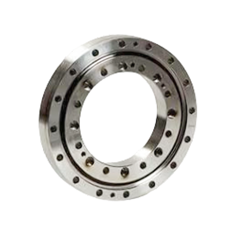
RE-type crossed cylindrical roller bearings are engineered for applications that demand high rotational accuracy, strong rigidity, compact dimensions, and reliable performance under combined loading. Their split-inner-ring and one-piece-outer-ring construction creates a bearing arrangement especially suitable for mechanisms in which the outer ring rotates while the surrounding housing remains stationary. This configuration is widely used in precision rotary tables, robotic arm joints, medical equipment, measuring instruments, semiconductor machinery, and intelligent automation systems.
Unlike conventional radial ball bearings, RE cross roller bearings can support radial loads, axial loads, and overturning moments with a single compact bearing assembly. Their rollers are arranged at right angles to one another in alternating directions. This arrangement allows the bearing to manage loads from multiple directions while maintaining a relatively small radial section. The result is a highly rigid rotary-support solution that can reduce the size, weight, and complexity of the host machine.
The principal dimensions of RE-type crossed cylindrical roller bearings correspond to the RB-type cross roller bearing family, while the bearing structure is optimized for applications requiring particularly high outer-ring rotational accuracy. The integrated outer ring reduces the number of separate components that must be aligned during assembly. When combined with controlled preload, precision-ground raceways, carburized bearing steel, nylon separators, and strict manufacturing inspection, the design provides stable rotation at micrometer-level accuracy.
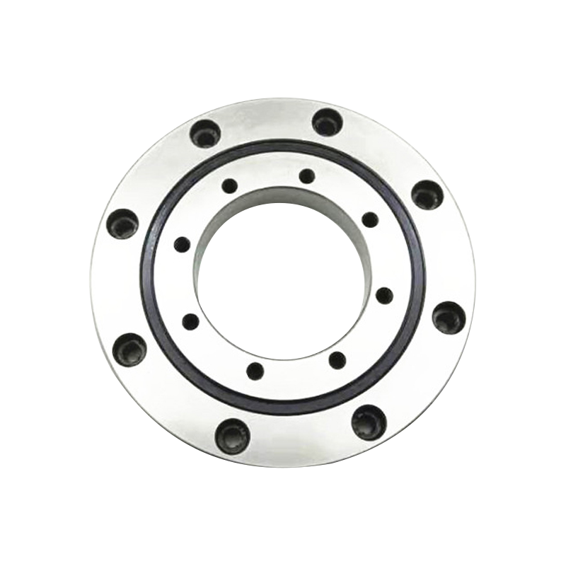
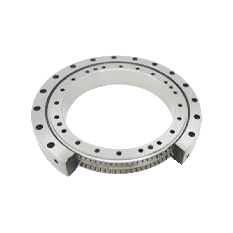
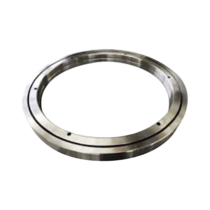
An RE cross cylindrical roller bearing consists primarily of an inner ring, an outer ring, cylindrical rollers, separators, and fastening components. The inner ring is split into two sections, while the outer ring is manufactured as one integral component. This arrangement allows the inner ring to be secured in the machine structure while the outer ring rotates with the supported member.
The one-piece outer ring is one of the most important characteristics of the RE design. Because the outer ring is manufactured and finished as an integrated component, the running geometry remains stable and accurately aligned. This is particularly valuable in rotary tables, robot joints, indexing mechanisms, and other systems where the outer ring must rotate with minimal runout.
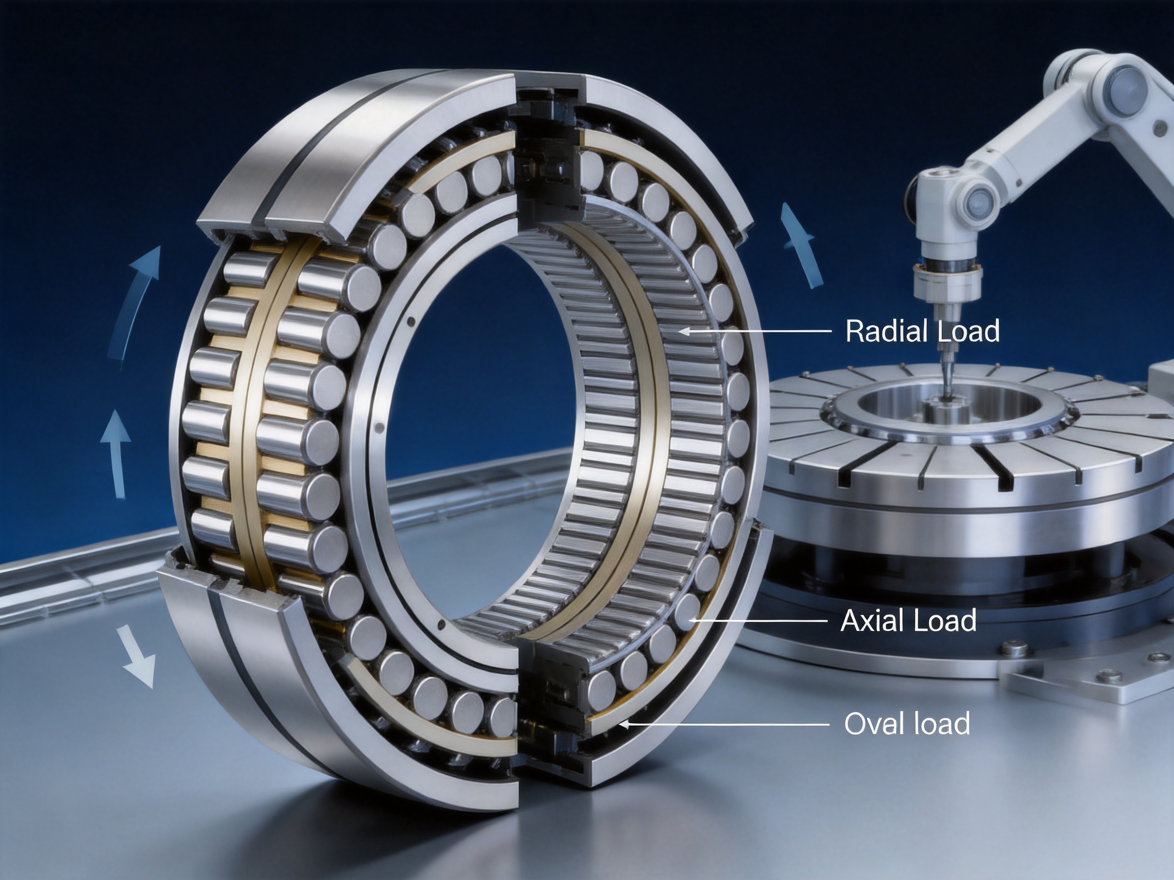
The rollers are arranged in a crossed pattern. One roller set carries load in one direction, and the adjacent set carries load in the perpendicular direction. This alternating arrangement allows the bearing to resist radial force, axial force, and overturning moment simultaneously. In many applications, one cross roller bearing can replace multiple conventional bearings, spacers, and preload mechanisms.
The bearing is supplied with an optimized preload. Preload removes internal clearance and improves the rigidity of the rotating assembly. It also helps reduce vibration, improve positioning repeatability, and limit elastic displacement under operating loads. Proper preload selection is essential because excessive preload may increase friction and heat, while insufficient preload may reduce stiffness and accuracy.
RE cross cylindrical roller bearings are available in compact sizes beginning with models such as RE 2008 and extending through larger bearing sizes in the supplied product range. Bore diameters in the listed RE series range from 20 mm to 130 mm. The available dimensional combinations provide designers with flexibility when selecting a bearing for limited installation space, high moment loading, or demanding rotary accuracy.
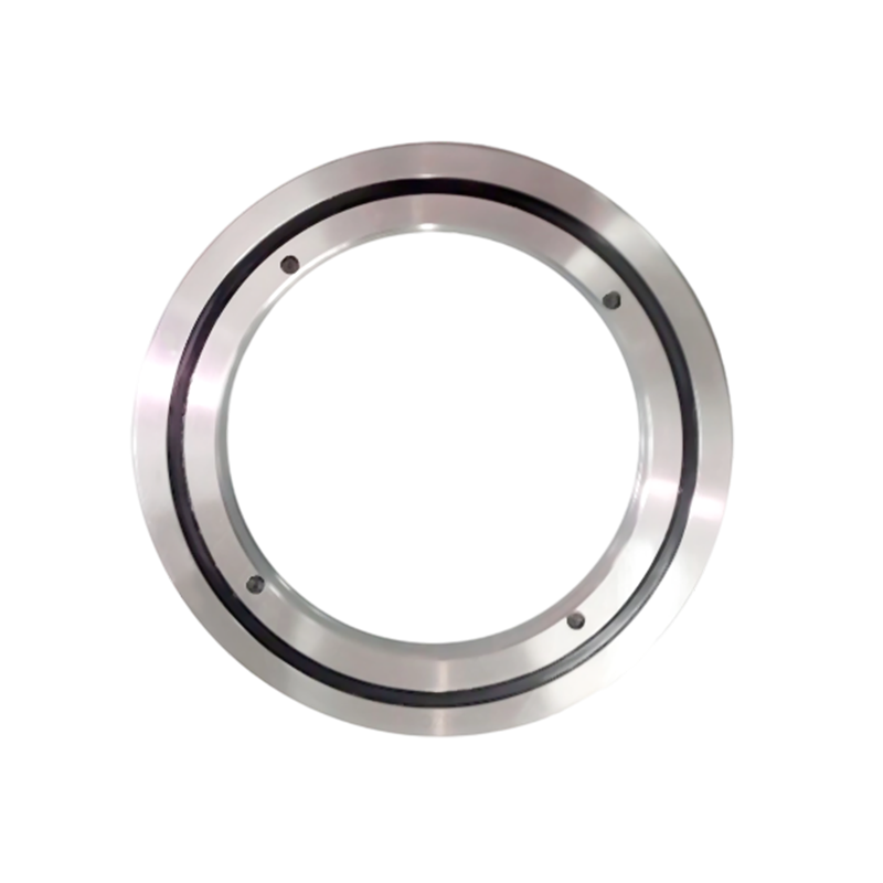
RE Cross Cylindrical Roller Bearing
In a conventional cylindrical roller bearing, the rollers normally carry loads primarily in the radial direction. In a cross roller bearing, the rollers are arranged alternately at approximately 90-degree orientations. One roller supports load in one direction, while the next roller supports load in the perpendicular direction. This geometry creates a bearing capable of carrying loads in several directions through a single raceway system.
The crossed roller arrangement is especially effective when overturning moments are present. An overturning moment creates a force couple across the bearing, placing increased load on one side of the bearing and reduced load on the opposite side. Because the roller pitch diameter is relatively large compared with the bearing cross section, the bearing can resist this moment efficiently. A larger effective span between the loaded areas increases moment capacity without requiring a proportionally larger bearing envelope.
The split-inner-ring structure simplifies installation into the housing or onto the shaft. The two inner-ring sections are secured together using supplied fastening components. Once properly secured, the bearing should be treated as a complete assembly. The internal separator arrangement and roller spacing are established during production, and arbitrary disassembly may disturb the internal running condition.
The one-piece outer ring provides a stable rotating reference surface. It is especially advantageous when the outer ring is connected directly to a rotary table, robot arm, or other moving structure. The integral design reduces the possibility of mismatch between separate outer-ring segments and helps maintain uniform raceway geometry around the complete circumference.
Compared with a design using multiple separate bearing rings, the RE structure can reduce assembly variation and simplify the machine designer’s housing arrangement. Fewer separate components may also mean fewer adjustment operations, fewer tolerance stack-up problems, and lower machining costs for the complete rotary mechanism.
Preload is controlled during bearing production to obtain a balance between rigidity, starting torque, running smoothness, and service life. The optimized preload used for RE bearings supports high positioning accuracy while maintaining practical rotational performance. It also reduces internal movement of the rollers when the bearing is subjected to vibration or reversing loads.
For precision rotary applications, preload is not simply a measure of resistance to rotation. It affects the entire dynamic behavior of the system. A properly preloaded bearing helps suppress small movements at the contact points, reduces mechanical play, and allows the control system to position the rotating component more consistently. This is important in robotic arms, inspection equipment, optical mechanisms, and automated indexing systems.
RE cross cylindrical roller bearings are designed for applications in which outer-ring rotational accuracy is a primary requirement. The integral outer-ring construction and precision-controlled raceway geometry help maintain smooth, stable rotation. Depending on the bearing specification and application conditions, precision grades can reach P4 and P2 levels.
High accuracy is valuable not only for maintaining geometric precision but also for improving process consistency. In a machine tool, lower radial and axial runout can contribute to improved machining quality. In a robot joint, accurate bearing movement can improve repeatability. In a measuring instrument, stable rotation can reduce errors caused by mechanical movement or vibration.
Rotational accuracy is influenced by more than the bearing itself. Shaft and housing tolerances, mounting surface flatness, bolt tightening sequence, lubrication, applied load, and thermal conditions all affect final performance. The RE bearing provides a high-precision foundation, but the surrounding machine structure must also be designed and manufactured to an appropriate standard.
Every bearing in this product family is supplied with preload. This feature gives the bearing high resistance to elastic deformation when the load changes. High rigidity is particularly important when a rotary assembly must hold a tool, gripper, workpiece, optical component, or measurement sensor in a fixed position.
The large roller contact area and crossed roller geometry distribute the load across numerous rollers. This reduces localized stress and allows the bearing to support demanding combined loads. The design is well suited to systems in which radial, axial, and moment loads occur simultaneously rather than independently.
High rigidity also improves control response. When a servo motor changes direction, excessive bearing deformation can create a delay between motor movement and load movement. A stiff bearing reduces this effect, allowing the control system to respond more accurately to commanded motion. This benefit is important in high-speed indexing, robotic positioning, and precision automation.
RE bearings can withstand axial loads, radial loads, and overturning loads. A conventional arrangement may require separate radial and thrust bearings, a support frame, and a dedicated preload mechanism to manage the same combination of forces. The cross roller design integrates these functions in one compact assembly.
The load rating table for the supplied products lists basic radial load ratings from approximately 3.23 kN for the RE 2008 model to 69.5 kN for the RE 13025 model. Actual allowable load depends on speed, lubrication, operating temperature, mounting accuracy, load direction, shock loading, and required service life. Designers should evaluate the complete load spectrum rather than selecting a bearing based only on static load capacity.
The thin-walled cross section saves space in the host machine. Compact dimensions can allow a larger hollow shaft, a smaller housing, a shorter machine frame, or more internal space for cables and pneumatic lines. In robotic joints, the compact profile can reduce the size of the moving arm and lower the inertia that the motor must accelerate.
Reducing the bearing envelope may also reduce the weight of the surrounding structure. A lighter rotary assembly requires less drive torque and may consume less energy during acceleration and deceleration. For automated equipment, this can improve cycle time and reduce the size of motors, gearboxes, and support structures.
The thin-walled design is also useful when the designer must preserve a large central opening. Hollow rotary tables and robot joints often need internal space for wiring, air lines, coolant lines, optical fibers, or other functional components. Cross roller bearings can support the required loads without occupying the full radial space of a conventional bearing arrangement.
The optimized internal structure and nylon separators help provide good rotational performance. The separators keep the rollers correctly spaced, reduce roller-to-roller contact, and contribute to smooth operation. Their relatively low mass produces low moment of inertia and low starting torque compared with heavier separator arrangements.
Low starting torque is beneficial in applications that require frequent indexing, rapid reversing, or sensitive servo control. The motor can begin movement with less resistance, while the control system can manage small angular increments more easily. Speed capability must still be evaluated against bearing size, lubrication method, temperature, preload, load, and duty cycle.
Nylon separators contribute to a low moment of inertia. This is especially valuable in angular indexing systems and robotic joints that repeatedly accelerate and decelerate. Lower rotating mass can reduce the energy needed to change speed and may improve the response of the servo system.
Reduced inertia can also help limit overshoot during positioning. When a motor stops or reverses, the machine must control the kinetic energy stored in the rotating components. A low-inertia bearing arrangement can make the system easier to tune and may reduce the mechanical stress associated with repeated acceleration cycles.
The bearing rings and rolling elements use carburized steel. Carburizing creates a hard wear-resistant surface while retaining a tougher and more impact-resistant core. This combination is suitable for bearing applications in which the raceway must resist surface fatigue and wear, while the overall component must tolerate shock and fluctuating loads.
Carburized steel is particularly useful in industrial machinery that experiences intermittent loading, vibration, or occasional impact. The material characteristics support long-term dimensional stability when the bearing is correctly mounted, lubricated, and operated within its design limits.
The following table summarizes representative RE-series dimensions and ratings from the supplied product information. Dimensions are shown in millimeters unless otherwise stated. Cr and Cor are basic radial load ratings in kilonewtons, and weight is shown in kilograms.
| Model | Inner Diameter d | Outside Diameter D | Roller Pitch Diameter Dpw | Height B | Chamfer Rmin | Shoulder ds | Shoulder Dh | Cr | Cor | Weight |
|---|---|---|---|---|---|---|---|---|---|---|
| RE 2008 | 20 | 36 | 29 | 8 | 0.5 | 23.5 | 30.5 | 3.23 | 3.10 | 0.04 |
| RE 2508 | 25 | 41 | 34 | 8 | 0.5 | 28.5 | 35.5 | 3.63 | 3.83 | 0.05 |
| RE 3010 | 30 | 55 | 43.5 | 10 | 0.6 | 37 | 47 | 7.35 | 8.36 | 0.12 |
| RE 3510 | 35 | 60 | 48.5 | 10 | 0.6 | 41 | 51.5 | 7.64 | 9.12 | 0.13 |
| RE 4010 | 40 | 65 | 53.5 | 10 | 0.6 | 47.5 | 58 | 8.33 | 10.60 | 0.16 |
| RE 4510 | 45 | 70 | 58.5 | 10 | 0.6 | 51 | 61.5 | 8.62 | 11.30 | 0.17 |
| RE 5013 | 50 | 80 | 66 | 13 | 0.6 | 57.5 | 72 | 16.70 | 20.90 | 0.27 |
| RE 6013 | 60 | 90 | 76 | 13 | 0.6 | 68 | 82 | 18.00 | 24.30 | 0.30 |
| RE 7013 | 70 | 100 | 86 | 13 | 0.6 | 78 | 92 | 19.40 | 27.70 | 0.35 |
| RE 8016 | 80 | 120 | 101.4 | 16 | 0.6 | 91 | 111 | 30.10 | 42.10 | 0.70 |
| RE 9016 | 90 | 130 | 112 | 16 | 1.0 | 98 | 118 | 31.40 | 45.30 | 0.75 |
| RE 10016 | 100 | 140 | 121.1 | 16 | 1.0 | 109 | 129 | 31.70 | 48.60 | 0.83 |
| RE 10020 | 100 | 150 | 127 | 20 | 1.0 | 113 | 133 | 33.10 | 50.90 | 1.45 |
| RE 11020 | 110 | 160 | 137 | 20 | 1.0 | 120 | 140 | 34.00 | 54.00 | 1.56 |
| RE 12025 | 120 | 180 | 152 | 25 | 1.5 | 133 | 164 | 66.90 | 100.00 | 2.62 |
| RE 13025 | 130 | 190 | 162 | 25 | 1.5 | 143 | 174 | 69.50 | 107.00 | 2.82 |
The supplied information also includes larger RB-designated sizes from RB 14016 through RB 1250110. These larger models belong to the same general cross roller bearing dimensional family but should be confirmed by model designation, drawing, and application requirements before being specified as RE products. Final selection should always be based on the manufacturer’s current dimensional drawing and technical confirmation.
A major advantage of a cross cylindrical roller bearing is its ability to support several load directions with one compact component. A conventional system may use a pair of angular contact ball bearings, a radial bearing, or a separate thrust bearing to obtain comparable load support. That arrangement can increase axial length, housing size, component count, and assembly complexity.
The RE bearing consolidates radial, axial, and moment support into one bearing envelope. This can simplify the mechanical design and improve the consistency of the final assembly. Fewer components also mean fewer interfaces that can introduce clearance, misalignment, friction, or tolerance variation.
Crossed cylindrical rollers generally provide a larger line-contact area than point-contact balls. The increased contact area enables high load capacity and high rigidity in a relatively small section. For equipment that must maintain position under load, this can be a meaningful advantage over a standard deep-groove ball bearing.
Angular contact ball bearings remain valuable in many applications, particularly when high speed or specific axial-load arrangements are required. However, where overturning moments, low runout, and compact structural integration are dominant requirements, a preloaded cross roller bearing may provide a more suitable solution.
When several bearings are arranged in tandem, the total axial length can become substantial. The thin cross-section of the RE design can reduce shaft length and housing width. A shorter shaft may also experience less bending deflection, provided the shaft diameter and structural stiffness are correctly designed.
Reduced axial length can lower machining costs, simplify sealing arrangements, and create more freedom for motor, encoder, and cable placement. It may also allow the designer to produce a lighter machine head or more compact robotic joint.
The integrated outer ring and preloaded internal structure can simplify assembly compared with a multi-bearing arrangement that requires separate spacers and carefully controlled adjustment. The bearing can be installed directly into a properly prepared housing or onto a suitable shaft arrangement.
Although installation is simplified, precision assembly remains essential. The housing must have the correct dimensional tolerance, adequate stiffness, and proper flange support. Mounting surfaces must be clean and flat, and tightening must follow the specified sequence and torque requirements.
UKL Bearing Manufacturing Co., Ltd. combines research and development, production, international distribution, and technical service. The company operates a modernized factory with production lines covering forging, turning, heat treatment, grinding, assembly, and packaging. This integrated process structure provides control over the complete bearing manufacturing chain.
The manufacturing process begins with carefully selected bearing steel. Forging forms the basic ring and roller blanks while improving material density and fiber flow. Controlled forging reduces internal defects and establishes a consistent foundation for subsequent machining operations.
Material traceability is important at this stage. Each production batch should be identifiable through its processing route, heat-treatment record, inspection results, and final assembly information. Strong traceability helps manufacturers investigate deviations, control repeatability, and support customer quality requirements.
After forging, the ring blanks are turned to establish the basic dimensions of the inner and outer rings. Turning creates reference surfaces for later grinding and prepares the raceway areas for heat treatment. Dimensional control during turning affects material allowance, concentricity, and the efficiency of later finishing operations.
Modern turning equipment can control diameter, width, shoulder geometry, and groove location with high repeatability. Stable tooling, controlled cutting parameters, and regular tool inspection help prevent variation between production batches.
Heat treatment gives the bearing rings and rollers the required hardness, toughness, and fatigue resistance. Carburizing is used to create a hard surface layer while preserving a tougher core. The process must be controlled carefully because excessive distortion can affect raceway accuracy and increase the amount of material that must be removed during grinding.
Important heat-treatment controls include furnace temperature, carbon potential, soaking time, cooling rate, tempering conditions, and process atmosphere. Hardness testing, metallographic examination, and dimensional inspection help verify that the material meets the required specification.
Grinding is one of the most critical stages in the production of high-precision bearings. The raceways, end faces, shoulders, and other functional surfaces are ground to achieve the required dimensional accuracy, roundness, waviness, and surface finish.
For cross roller bearings, raceway geometry must be controlled consistently around the complete ring. Small variations can influence roller contact, preload, torque, temperature, and rotational accuracy. Precision grinding equipment, stable coolant control, balanced dressing procedures, and accurate measurement systems are therefore essential.
Grinding also establishes the final relationship between the inner ring, outer ring, and roller set. The accuracy of these relationships directly affects the bearing’s ability to maintain smooth movement and resist moment loads.
Assembly includes cleaning, roller placement, separator installation, ring matching, fastening, lubrication, and inspection. The rollers must be installed in the correct crossed orientation and spacing. The internal components must remain free of contamination, burrs, and foreign particles.
Preload is established and verified during assembly. The process may include torque measurement, starting torque measurement, rotational inspection, dimensional checks, and runout testing. Consistent preload control is essential because the bearing’s rigidity and operating behavior depend strongly on its internal condition.
Before shipment, finished bearings are inspected for appearance, dimensions, rotational behavior, and identification. Depending on the product specification, inspection may include radial runout, axial runout, starting torque, noise, vibration, hardness, raceway condition, and preload verification.
Clean packaging protects the bearing from moisture, dust, corrosion, and impact during storage and transportation. Proper packaging is particularly important for precision bearings because contamination or damage to a raceway can affect performance even when the external appearance seems acceptable.
UKL maintains an R&D focus on high-precision cross roller bearings, dual-direction thrust angular contact ball bearings, and other products for CNC machinery, robotics, and intelligent automation. Engineering capability supports product customization, application evaluation, dimensional adaptation, and technical assistance during equipment development.
For OEM customers, the ability to discuss a bearing with both manufacturing and engineering teams can reduce development time. Important design factors include load spectrum, moment loading, rotation speed, indexing frequency, environmental conditions, lubrication, installation accuracy, expected life, and required accuracy grade.
Rotary tables require high stiffness, low runout, and accurate angular movement. An RE bearing can support the table while resisting radial forces, axial forces, and overturning moments generated by the workpiece or cutting tool. Its compact design also preserves space for drive systems, encoders, and central cable passages.
In CNC equipment, bearing accuracy contributes to table positioning and machining consistency. The bearing should be installed on accurately machined mounting surfaces, and the table structure should be sufficiently rigid to prevent deformation from being transferred into the raceways.
Robot joints experience reversing motion, acceleration, deceleration, radial loads, and large overturning moments. The RE bearing’s high rigidity and low starting torque make it suitable for compact joints in industrial robots, collaborative robots, assembly systems, and automated handling equipment.
Reducing joint weight is important because every gram saved in an outer link can reduce the required torque at upstream joints. A compact cross roller bearing can contribute to a lighter and more responsive robot architecture while supporting the precision required for repeatable movement.
Medical equipment often requires quiet movement, compact construction, reliable positioning, and controlled cleanliness. Cross roller bearings can be used in imaging systems, patient-positioning mechanisms, surgical equipment, laboratory automation, and diagnostic instruments.
Material selection, lubrication, sealing, cleaning, and regulatory requirements should be evaluated for each medical application. The bearing should be specified according to the complete device environment rather than selected only from a dimensional catalog.
Measuring systems depend on stable, repeatable movement. Runout, vibration, and mechanical play can introduce measurement errors. A preloaded RE bearing helps reduce unwanted movement and supports accurate rotation in optical stages, coordinate measurement systems, inspection instruments, and precision positioning platforms.
Semiconductor machinery and automated production equipment often require compact mechanisms with high repeatability and low particle generation. The bearing can support rotary stages, wafer-handling mechanisms, inspection platforms, and automated indexing devices. Application-specific lubrication and cleanliness controls are necessary where contamination limits are strict.
Correct installation is essential for obtaining the designed accuracy and service life of an RE cross roller bearing. The housing, shaft, flange, and mounting surfaces must be manufactured within the specified tolerances. Improper mounting can cause raceway deformation, uneven preload, increased torque, noise, premature wear, and reduced rotational accuracy.
Inspect the bearing, shaft, housing, flange, bolts, and mounting surfaces before assembly. Remove machining chips, dust, burrs, rust inhibitors that are incompatible with the selected lubricant, and other contaminants. Confirm that the bearing model matches the drawing and that no component has been damaged during transportation.
Measure the key housing and shaft dimensions where necessary. Check flatness, roundness, shoulder height, and the condition of locating surfaces. The side-clamping flange must be capable of firmly securing the appropriate bearing ring without distorting it.
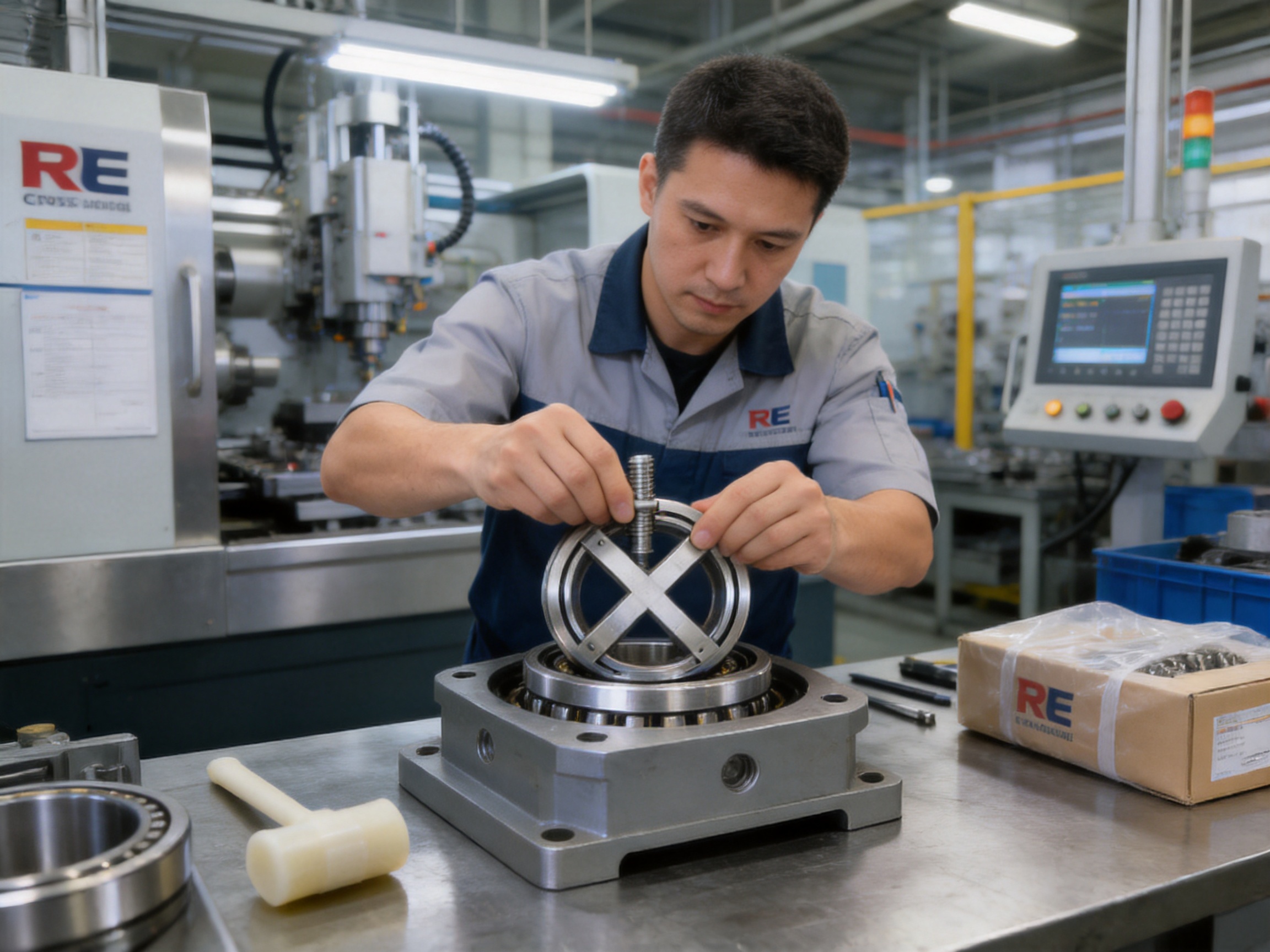
The joint between a split inner ring may sometimes be slightly misaligned before installation. If this occurs, loosen the bolts securing the ring and correct the joint carefully using a plastic hammer. The correction should be gentle and controlled. Do not use a steel hammer directly on the bearing ring, and do not force the ring into alignment with excessive impact.
After the ring has been correctly aligned, install it into the housing or onto the shaft according to the bearing arrangement. The bearing should not be disassembled to correct an installation issue unless the manufacturer provides specific instructions.
Do not apply external force directly to the connecting bolts during installation or disassembly. The bolts are intended to secure the bearing ring and should not be used to pull a misaligned bearing into position. Tighten the bolts gradually in a crosswise or sequential pattern so that the ring is seated evenly.
Use the specified bolt grade, thread condition, tightening torque, and tightening sequence. If the application requires a particular torque or clamping procedure, follow the approved technical drawing or installation manual. Uneven tightening can distort the bearing ring and change the preload distribution.
RE bearings should be adequately lubricated with a grease or oil compatible with the operating speed, load, temperature, and environmental conditions. The lubricant must be distributed through the roller tracks without creating excessive churning. Too little lubricant may increase wear and temperature, while too much lubricant may increase torque and heat.
Lubricant compatibility should be confirmed before mixing products. Different greases may use incompatible base oils, thickeners, or additives. During maintenance, remove degraded or contaminated lubricant where practical and replenish the bearing according to the operating schedule.
Routine maintenance should include monitoring torque, noise, vibration, temperature, runout, and positioning performance. A gradual increase in starting torque may indicate lubricant degradation, contamination, mounting deformation, or raceway damage. Changes in noise or vibration may indicate roller or raceway distress.
Operating temperature should be evaluated in relation to speed, preload, lubricant, ambient conditions, and heat transfer through the housing. A small temperature increase during initial operation may be normal, but an unexpected or continuously rising temperature requires investigation.
Keep the bearing protected from moisture, dust, corrosive chemicals, and impact. Sealing and shielding arrangements should be selected according to the application environment. In exposed mechanisms, contamination control may be as important as bearing load capacity.
Replacement intervals should be based on actual operating conditions rather than calendar time alone. Load spectrum, duty cycle, speed, oscillation angle, lubrication, and environmental conditions all affect service life. In high-value equipment, condition monitoring can help identify changes before a bearing failure interrupts production.
The RE cross cylindrical roller bearing offers a combination of accuracy, stiffness, compactness, and integrated load support that aligns well with modern machine design. It can reduce the number of bearings required in a rotary assembly, shorten the structure, improve positioning response, and provide a stable platform for servo-controlled movement.
UKL Bearing Manufacturing Co., Ltd. supports OEM and distributor customers with production capacity, engineering development, and international service. The company reports a monthly production capacity of approximately 10,000 to 50,000 units and serves customers in North America, Europe, Asia, Africa, and other markets.
Its production capabilities include forging, turning, heat treatment, grinding, assembly, and packaging. This broad process coverage helps maintain consistency from raw material preparation through finished-product inspection. The company also supports customized bearing development for specialized equipment and application requirements.
Technical service includes application consultation, installation guidance, and after-sales support. For customers developing a new rotary mechanism, early consultation can help determine the correct bearing size, preload, accuracy grade, mounting method, lubrication, and inspection criteria.
The company also emphasizes environmentally responsible production, material recycling, energy optimization, and technical training. These practices support a long-term manufacturing strategy in which product performance, production efficiency, and responsible resource use are considered together.
When selecting an RE bearing, begin with the required bore diameter, outside diameter, height, and available installation space. Next, calculate the radial load, axial load, overturning moment, speed, acceleration, and operating temperature. The most demanding load case should be used for verification.
Consider whether the outer ring or inner ring rotates. RE bearings are particularly suitable for structures requiring high outer-ring rotational accuracy, but the mounting arrangement must be confirmed carefully. The direction of rotation, load distribution, and connection between the bearing ring and machine structure all affect performance.
Choose an accuracy grade according to the machine’s positioning and runout requirements. P4 or P2 precision may be appropriate for high-precision machinery, but the surrounding components must have matching accuracy. A highly accurate bearing cannot compensate for a distorted housing, poor shaft geometry, or inadequate mounting surface.
Evaluate the required rigidity and preload. High preload can improve stiffness and positioning response, but it may also increase friction and heat. The correct balance depends on speed, duty cycle, load, and control requirements.
Finally, specify the lubrication, sealing, inspection, and packaging requirements. Applications involving dust, coolant, vacuum, cleanroom operation, or elevated temperature may require special technical arrangements. A complete specification improves the chance of obtaining stable performance in the final machine.
An RE cross cylindrical roller bearing is a precision bearing with a split inner ring, one-piece outer ring, and cylindrical rollers arranged alternately at right angles. It supports radial loads, axial loads, and overturning moments while maintaining a compact radial section.
RE and RB bearings belong to the same general cross roller bearing family and may share principal dimensions. The RE configuration uses a split inner ring and integral outer ring, making it especially suitable for applications that require high outer-ring rotational accuracy. The exact structural and mounting details should be confirmed from the manufacturer’s drawing.
Once the split ring has been secured with the appropriate bolts and nuts, it should not be separated casually. The internal rollers and separators are arranged for a controlled running condition. Arbitrary disassembly may affect roller spacing, preload, and rotational performance.
Yes. The crossed roller arrangement allows the bearing to support radial and axial forces simultaneously. It can also resist overturning moments. The permissible load must be calculated using the actual operating conditions and the manufacturer’s technical recommendations.
Preload removes internal clearance and increases rigidity. It helps reduce mechanical play, vibration, and elastic displacement during load changes. However, excessive preload may increase friction and temperature, so the specified preload must be preserved during mounting.
They can provide good rotational speed capability when correctly selected and lubricated. Actual speed limits depend on bearing size, preload, load, lubrication, temperature, and duty cycle. High-speed applications should be reviewed by a technical engineer before production release.
The supplied information identifies carburized steel as a key material for impact resistance and surface wear resistance. Nylon separators are used to maintain roller spacing while contributing to low moment of inertia and low starting torque.
Typical applications include precision rotary tables, robotic arm joints, medical devices, measuring instruments, CNC machinery, semiconductor equipment, optical stages, and intelligent automation systems.
Check the model, dimensions, shaft and housing tolerances, mounting surface flatness, shoulder dimensions, cleanliness, lubricant compatibility, bolt condition, and installation sequence. Confirm that the flange can clamp the correct ring firmly from the side.
Loosen the securing bolts and correct the joint carefully with a plastic hammer before installation. Do not use excessive force, do not strike the bearing directly with a steel hammer, and do not use the connecting bolts to force a misaligned ring into position.
OEM customization may be possible depending on the required dimensions, accuracy, preload, lubrication, material, packaging, and production quantity. The complete application specification should be reviewed before confirming a customized design.
Use correct mounting tolerances, adequate lubrication, proper sealing, controlled preload, suitable operating loads, and regular condition monitoring. Prevent contamination and avoid shock loads beyond the bearing’s design capability.
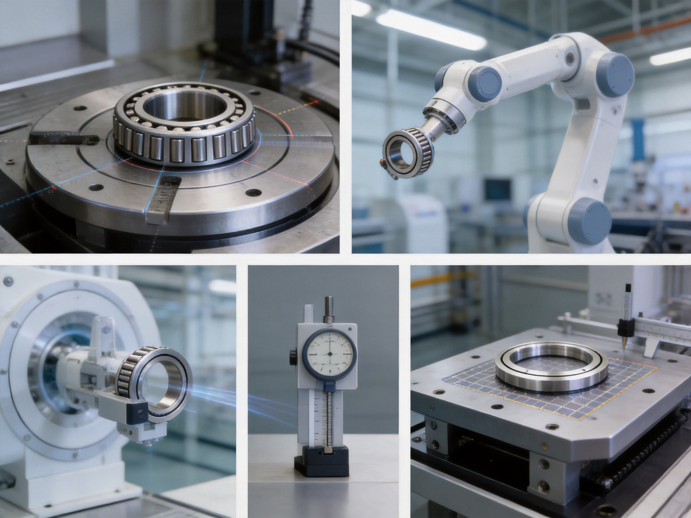
RE cross cylindrical roller bearings provide a strong solution for precision rotary mechanisms that require high accuracy, rigidity, compact construction, and multi-directional load capacity. Their split-inner-ring and one-piece-outer-ring structure is particularly effective when outer-ring rotational accuracy is important. Crossed cylindrical rollers support radial loads, axial loads, and overturning moments through one integrated bearing assembly.
The product’s advantages include P4 and P2 precision options, optimized preload, high rigidity, low starting torque, low moment of inertia, strong impact resistance, high load capacity, and reduced structural size. These features make the bearing suitable for robotics, rotary tables, medical machinery, measuring equipment, CNC systems, and intelligent automation.
UKL Bearing Manufacturing Co., Ltd. adds value through integrated manufacturing processes that include forging, turning, heat treatment, grinding, assembly, and packaging. Its R&D capabilities, production capacity, international service network, and OEM/ODM experience support customers seeking dependable bearing solutions for both standard and specialized equipment.
For the best result, bearing selection must be combined with accurate shaft and housing design, correct installation, suitable lubrication, and disciplined maintenance. When these conditions are controlled, an RE cross cylindrical roller bearing can provide stable, precise, and durable rotary support for demanding industrial applications.
1. Manufacturer-supplied RE Cross Cylindrical Roller Bearing Product Information and Dimensional Tables.
2. Manufacturer-supplied Installation, Handling, Lubrication, and Maintenance Guidance for Cross Roller Bearings.
3. ISO 76, Rolling Bearings—Static Load Ratings.
4. ISO 281, Rolling Bearings—Dynamic Load Ratings and Rating Life.
5. ISO 199, Rolling Bearings—Thrust Bearings—Geometrical Product Specifications and Rating Principles.
6. General Engineering Principles for Precision Rotary Tables, Robotic Joints, and Cross Roller Bearing Applications.
7. Bearing Steel Heat Treatment and Carburizing Practices for High-Load Rolling Contact Components.
Product Categories
Contact Us

Jane@ukl-bearing.com
Jenny@ukl-bearing.com
Andy@ukl-bearing.com
Ivy@ukl-bearing.com

+86-510- 88763239
+86-15371057968

No.1 Hehuan Road, Hudai Town, Binhu District, Wuxi City.
Ready to Begin?
Get in Touch

Now!
UKL BEARING
 English
 Español
 русский